I’ve written my last two blogs about different pitfalls and insight needed in order to properly translate CAD data. I’ve discussed how “sharing” of geometry inside the data structure is a hidden but much used form of design intent and discussed how geometry forms are inherently linked to high-level algorithms inside the modeler itself. But I haven’t discussed the healing operations that the Spatial translators perform in order to properly translate the different CAD formats. If you use our translators you know they exist, and people commonly ask about their purpose and efficacy.
To understand InterOp healing we have to start by borrowing a concept from any undergraduate Data Structure and Algorithms class. Generally, one views a software system as two distinct but highly inter-related concepts: a data structure and an acting set of algorithms or operators. In our case the data structure is a classic Boundary Representation structure (B-rep) which geometrically and topologically models wire, sheet and solid data. An operator is an action on that data, for example, an algorithm to determine if a point is inside the solid or not. But the system’s operators are more than just a set of actions. Implicitly, the operators define a set of rules that the structure must obey. Not all the rules are enforced in the structure itself; actually, many can’t be. But they exist and it’s healing in InterOp that properly conditions the B-rep data to adhere to these rules upon translation.
As always a couple of examples best describe the point. I picked three ACIS rules that are, hopefully, easily understandable.
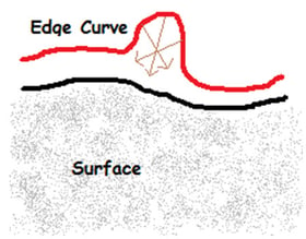
All 3d edge geometry must be projectable to the surface. Anybody can define a spline based EDGE curve and a surface and write it to SAT. Basically, jot down a bunch of control points, knot vectors, what have you, and put it in a file that obeys SAT format. But in order for it to work properly, geometric rules for edge geometries exist. Specifically, the edge geometry must be projectable to the surface. In short, you can’t have this:

There are many reasons in ACIS for this, but primarily if it’s not projectable then point-perp operations are not well-behaved. If they’re not well behaved finding the correct tolerance (distance between the curve and the surface) is problematic. If one cannot define correct tolerances then water-tightness is not achieved and simple operators, like querying if a point is inside the body, fail.
Edge and Face geometry cannot be self-intersecting. A great deal of solid modeling algorithms work by firing rays and analyzing intersections with different edge and face geometries. In order for any conclusion to be drawn, the results of the intersection must be quantifiable. The problem with self intersecting geometries is just that; how to you quantify the results in Figure 3? The key observation here; imagine you are walking along the curve in Figure 3, starting from the left side. At the start, the material is on the right side, but after the self intersection the material changes to the left side. You cross the self intersection again and the material switches to the right again. This causes endless grief in understanding the results of an intersection.

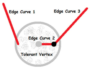
Tolerances of Vertices cannot entirely consume neighboring edges. For a B-rep model to be considered water-tight, tolerances of faces and edges must be understood. Today many kernels have global tolerances plus optional tolerances applied to edge curves and vertices. These tolerances vary depending on neighboring conditions, usually obeying some upper bound. You can think of these tolerances as the “caulking” that keeps the model water-tight. Depending on the quality of the geometry or the tolerances of the originating modeling system you might need more “caulking” or less; respectively, larger tolerances on edges or vertices, or smaller tolerances. However in order to realize a robust Boolean engine, again, rules apply. Consider this:

Above we have Edge Curve 2 encapsulated completely inside the gray tolerant vertex. Again, I can easily write this configuration to SAT format, however Booleans cannot process it. It yields horrific ambiguity when building the intersection graphs in the internal stages of Booleans.
So this is a list of just three rules, it’s far from being comprehensive. But the main point: we know that not everything that ends up in an IGES file comes from a mathematically rigorous surfacing or solid modeling engine. Perhaps people are translating their home-grown data into a system like ACIS so they can perform operations that they could not in their originating system. But in order to perform these operations, the data must conform to the rules of the system. To simply marshal the data and obey a file format, but disregard the rules, is doing just half the job.
That’s why healing matters.

