In this article, we discuss meshing and its use in both Computational Fluid Dynamics (CFD) and Finite Element Analysis (FEA). We also touch on some of the more common—yet surprisingly critical—mistakes that may be impeding your analysis. And finally, we’ll share tips on how to improve these processes.
What Is Meshing and Types of Meshes
‘Meshing’ (also known as ‘mesh generation’) is the process by which a continuous geometric shape is subdivided into a grid of elements.
There are two basic element types that make up a surface mesh.
- In 2D space, these are quadrilaterals (quad mesh) and triangles (tri mesh);
- In 3D space, they are hexahedrons (hex mesh) and tetrahedrons (tet mesh), respectively.
Each element belonging to a surface mesh is, by definition, connected to the elements around it; their shared corners are referred to as nodes. Structured mesh is usually composed of quad/hex elements, whereas unstructured meshes are typically made up of tri/tet elements.
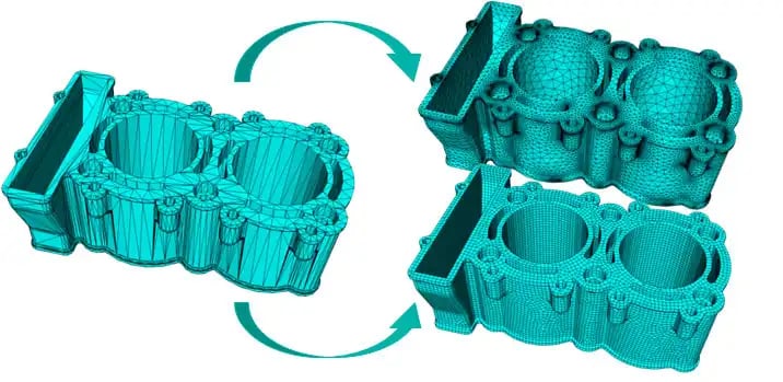
Meshing is a vital step in solving the complex object geometry of any 3D CAD model. It’s also synonymous with a more general mathematical process known as discretization—the act of transforming any continuous object, model, function, or equation into discrete components.
When a CAD object is discretized, each grid element represents a solution to the corresponding partial differential equations (PDE). When these solutions are combined across the entire grid, the result is a mesh-wide solution that describes the object as a whole.
Keep reading to understand the importance of meshing to simulation accuracy and how you can optimize your meshes.
Defining Everything From 3D Toolkits to X_T File Formats
Get simple explanations for common CAD/CAM terms, files formats, file conversions, and more.
Visit Glossary
The Importance of Meshing in CFD and FEA
But why is meshing so important? Meshing is important because it allows designers and engineers to create predictive models of real-world situations computationally—the more accurate the mesh, the more performant the simulation will be.
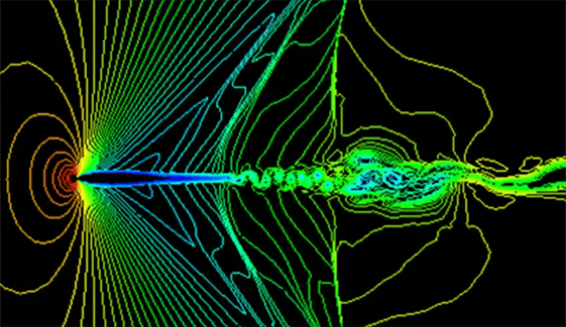
Both FEA and CFD are mathematical methods that rely on high-quality meshing. Though there are some exceptions, an FEA mesh is typically used for structural analysis, while CFD meshing is designed to solve fluid dynamics applications, like fluid flow problems.
For instance, if you were to simulate an airplane wing in action, a CFD mesh could be used to predict fluid forces like drag and lift, while finite element meshing could be used to analyze structural forces such as stress, strain, and deflection.
The Benefits of High-Quality Mesh in CFD and FEA
High-quality meshing is indispensable to maximizing the accuracy and minimizing the resources required for CFD and FEA tasks. Let’s look at some of the specific advantages of a high-quality mesh.
- Increased simulation validity
- Increased reliability across simulations
- Optimal convergence
- Reduced solve time
The Impact of Low-Quality Mesh in CFD and FEA
Steer clear of low-quality mesh at all costs. Errors at this stage of the process can lead to:
- Inaccurate simulation results
- Low-quality or illegal cells leading to instability
- Decreased reliability across simulations
- Bad convergence
- Long solve times
- A lot of wasted time, money, and manpower
Call-out/Tip
Before even generating a mesh, there are four design pillars your object must conform to. The Mesh should be:
- As simplified as possible
- Contain well-defined boundaries
- Be clean and without defects
- Be geometrically watertight
Observing these four commandments will put you on the right path to generating high-quality mesh every time.
5 Tips to Create a CFD/FEA Mesh That Improves Simulation Accuracy (Without Overburdening Sim Resources)
Now that we’ve discussed the importance of mesh quality, let’s look at some simple ways you can improve your mesh and increase simulation accuracy.
1. Increase Mesh Density at Critical Areas
Inflating mesh density across the entire model will not necessarily produce more accurate results. It will raise the computational cost significantly without a proportional rise in simulation accuracy. Conversely, a mesh lacking detail will provide rapid analysis but will leave you with imprecise results.
Instead, focus on selectively increasing mesh refinements at critical areas.
Call-out/Tip
A critical area is defined as any part of the object that is subject to high stress. By performing mesh refinement —specifically, by decreasing the size of structured hex elements—in those locations, you can boost accuracy without severely impacting computational cost.
2. Automate Meshing to Reduce Variation, and Human Error
Meshing can be a long and painstaking process when performed manually. Luckily, sophisticated automatic meshing software now exists. Not only does it substantially improve simulation accuracy, but it also reduces the time, effort, and—let’s face it—the likelihood of human error.
Spatial’s 3D Precise Mesh is an automatic and reliable meshing tool that gives users the ability to control the final output. This lets developers spend more time on innovation and less time on tedious workflows. Simply set your parameters and let 3D Precise Mesh take care of the heavy lifting.
3. Refine the Boundary Layer
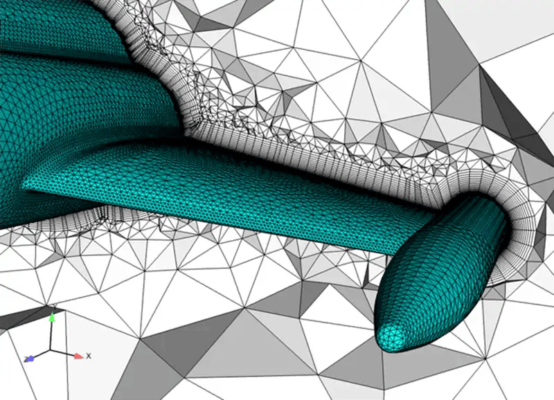
Refining the boundary layer is especially pertinent when performing CFD turbulence modeling. A boundary (represented by Y+) is a non-dimensional space that resides along the object’s edge where flow occurs.
Put another way, Y+ represents the ratio between turbulent and laminar influences on an element. A large Y+ value indicates that the element is turbulent; a small Y+ value means that the element is laminar.
Basically, boundary layer refinement boosts accuracy along the domain’s internal/external surface. Additionally, it maintains Y+ (our dimensionless wall distance value) for the appropriate turbulence model.
Keep in mind that file conversions can negatively affect boundary layers; however, this can be mitigated with the help of a dedicated CAD/CAM file conversion tool that preserves metadata and reduces the risk of translation errors.
4. Conduct a Mesh Convergence Study
As we know, coarse mesh fails to capture the flow characteristics needed for accuracy, whereas fine mesh improves accuracy but takes a toll on computational power and time.
A mesh convergence study is used to determine the number of grid elements necessary to ensure that mesh size changes do not influence analysis results. A convergence study isolates the perfect size for finite element meshes, thus converging upon a repeatable solution.
Once your study is complete, you’ll have attained what’s known as mesh independence. This means that any additional mesh refinement is unnecessary and won’t impact your results. You’ll have the certainty that your finite element mesh is not only accurate but optimal in terms of solve time.
5. Reduce Downstream Effort
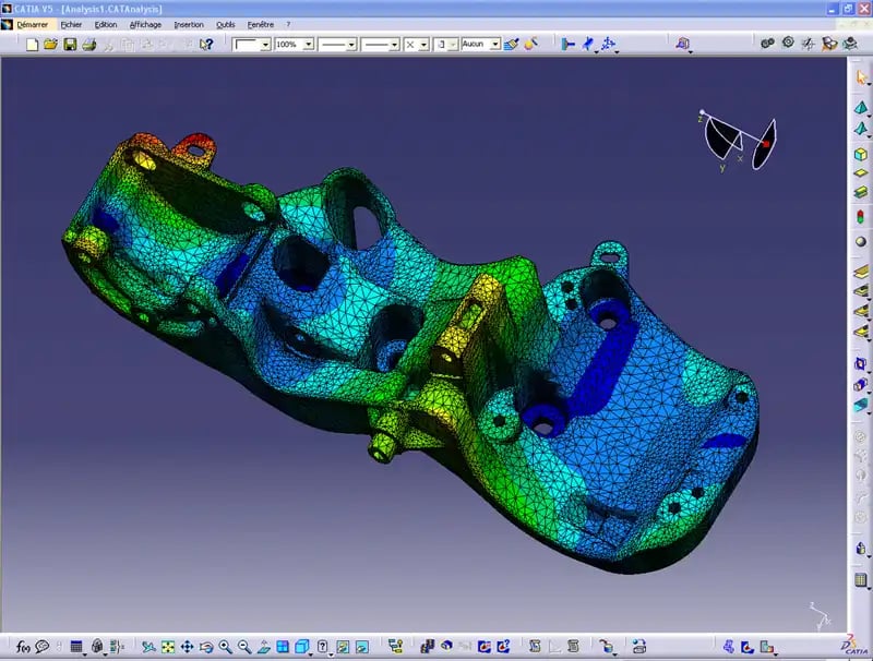
Reducing downstream effort is about optimizing 3D models during the engineering stage to ensure accurate simulations and translations later. While it’s true that the previous four steps all contribute to reducing downstream effort, there are other, more proactive ways to accomplish this.
Using advanced translation tools like 3D InterOp can better preserve object geometry while reducing import errors and defects. With Spatial’s innovative 3D solutions, you can always count on accurate and reliable file translations between CAD systems.
Optimize Your Computational Fluid Dynamics Mesh and Finite Element Analysis Mesh, With Spatial
At Spatial, we’ve been specializing in 3D modeling for over 35 years. In that time, we’ve helped 400+ businesses cut costs, reduce development time, and increase simulation accuracy.
Partner with Spatial and discover how you can improve your technological prowess with our line of cutting-edge 3D applications. Ready to see what true simulation-driven design looks like? Contact us today for your free value-added assessment.
