

Computational Fluid Dynamics (CFD) is a type of analysis that provides insight into solving complex problems, and allows engineers the ability to test the effects of fluid flow on their designs - this is done without the need to conduct real-world experiments.
CFD can help simulate aerodynamics, thermal heat transfer, and turbulent flow on 3D models by automating mathematical principles like Partial Differential Equations (PDE) and navier stokes.

CFD in everyday life
CFD analysis has proven more helpful in day-to-day, real world applications; especially given the wide range of use case across various industries - including architecture, vehicle design, petroleum engineering, surgery and meteorology.
While this form of analysis still requires ongoing improvements, technologies (and the individuals who run it) are getting better everyday.
With CFD software solutions architects can design safe and more comfortable living environments; while vehicle designers can improve the aerodynamics of the vehicles they produce. In addition, surgeons can cure arterial diseases through computation hemodynamics, while meteorologists can forecast the weather more accurately and warn us of impending natural disasters.
Stages of CFD analysis
CFD analysis consists of three main steps: pre-processing, processing and post-processing - here is a brief introduction to each of them.
1. Pre-processing
Pre-processing is the first step in CFD simulation - which can help to define the parameters of the simulation in an accurate way, if done properly.
In this step, you will need to identify the domain of interest and divide it into several small segments – this includes preparing the geometry, meshing it, defining the properties of the materials involved, and setting the boundary layer and conditions.
Critical Elements of Pre-Processing
As mentioned above, CFD analysis is only as good as its implementer - that is, how accurate can the designer set up (or pre-process) the model - as the initial design will eventually affect the model in the later phases of analysis.
It is crucial for the designer to ensure that the geometric model is free of errors or defects; Common issues involve:
- Gaps in the model
- Missing or overlapping faces
- Unclosed geometries like free faces, edges and vertices
After preparation the model should be a “closed” solid, void of any of the above mentioned errors. Once this is completed there are several additional steps to pre-processing for your CFD analysis.
Problem Analysis
Problem analysis is the cornerstone of your simulation - you need to understand the problems you are trying to solve for in order to properly define your objective and parameters.
Ask yourself “what are the physics of the problem I am trying to solve”? Are you trying to analyze the laminar and turbulent flow of blood through the veins as it adjusts to a change in pressure? Or are you evaluating the heat transfer of a new kitchen appliance design?
With accurate problem analysis you will be able to define your model with the right attributes in order to avoid incorrect data in your simulation results.
Geometry
Once you have your physics defined you must create a two or three-dimensional geometry that is dependent on your problem analysis.
Some problems are solvable in two dimensions, which can save time and money through reduced computational needs. Tools like Autodesk Inventor, Spaceclaim, CATIA, Solidworks or Design Modeller will be more appropriate for three-dimensional models - while Design Modeler and GAMBIT are better suited for two-dimensional needs.
Meshing
Meshing requires a great deal of care because it can have a cascading effect on your analysis if done improperly. This step involves establishing the physical domain of your environment into defined regions called cells, or control volumes.
These cells are further defined by the fluid flow equations inside the govern them - requiring the designer to make an educated assumption about their flow profiles (it is always best to start with a rough mesh and then refine it over time for specific areas).
Most designers find that keeping these cells as small as possible can help you ensure accuracy throughout the analysis.
Setup Solver
In this stage you will have to define the conditions of the problems you want to solve. For example, transient one-phase, stationary or multiphase, turbulence model, fluid type and boundary conditions.
It is essential to know the physics of your problem because the numerical solutions are pre-configured. Moreover, you have to know how the method works. When it comes to processing, you can choose the processors to use and the necessary iterations when it comes to achieving the convergence.
Results
The last piece of the pre-processing puzzle involves validating your set-up - you can achieve this by assessing experimental or analytical results. Having an understanding of problem physics can be the difference here, as it is difficult to make recommendations before you prove that the results are, in fact, accurate.
Software development kits from Spatial can accelerate and improve pre-processing of the following:
- CAD cleanup
- Mesh generation
- Automatic boundary layer generation
- CAD associativity to maintain material properties set by the designer (in CAD or intake/exhaust grouping)
2. processing
Every simulation process through a CFD program has to follow a defined set of steps. After all, simulations are a set of steps that must be complied with - as these set guidelines help to avoid getting stuck or receiving error messages in subsequent stages.
Lastly, each of these steps are interdependent on one another, which is why proper pre-processing is so critical to being with.
3. Post-processing
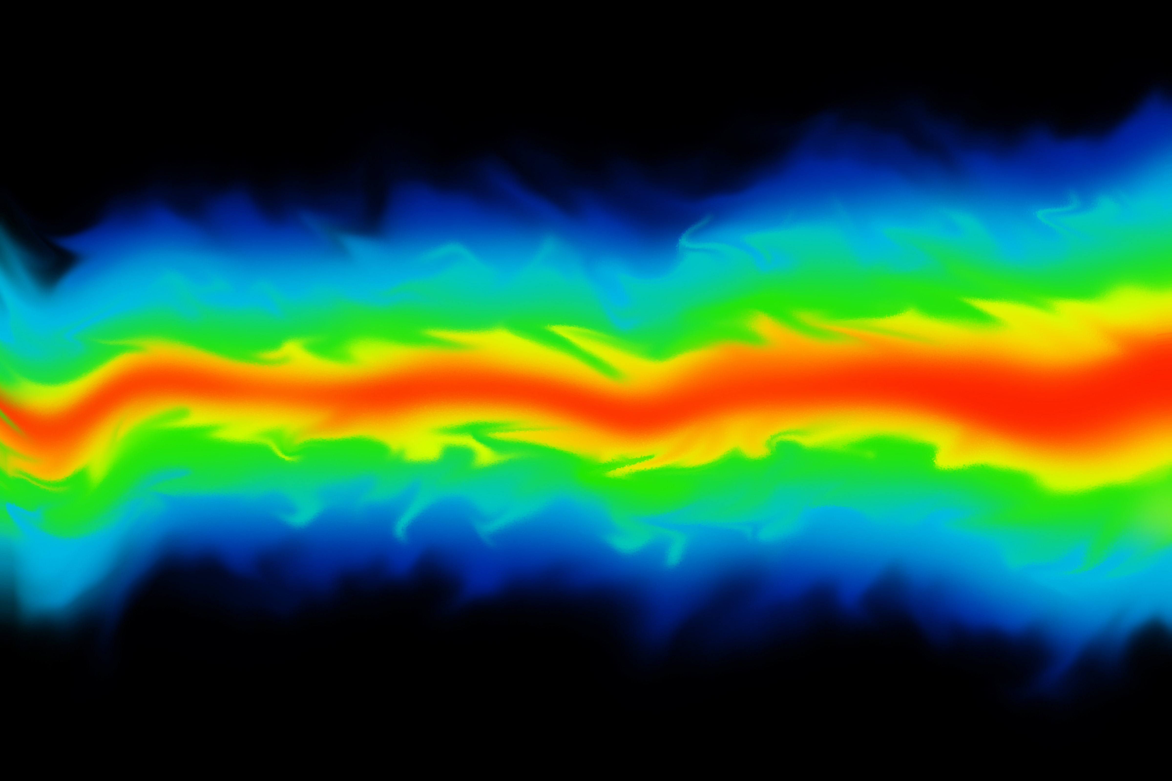
After getting results in the simulation stage, your next step is to analyse those results. Use the available methods such as vector plots, contour plots, data curves and streamlines to achieve this.
That way, you will get accurate reports and graphical representations. Some of the popular software tools used in the post-processing stage include EnsSight, ANSYS CFD-POST, ParaView, FieldView and Tecplot 360. Processes in this stage include:
- Calculation of the derived quantities
- Calculation of parameters
- Visualization
- Systematic data analysis and
- Debugging, verification and validation of the CFD model
The Future of CFD Analysis
Computational fluid dynamics has found wide application in the modelling of fluid flows, and has become a vital step in designing various machinery, tools and components - such as analyzing laminar and turbulent flow through water pumps and reducing ship drag.
As a rule of thumb CFD does not replace real world testing, however it does reduce the number of experiments needed in prototyping and testing (and with that, the overall cost and risks associated).
CFD analysis in a CAD environment gives engineers, designers and scientists the invaluable ability to visualize fluid flow attributes before physical creation, giving them a host of benefits over traditional experimentation - and we’re just scratching the surface, with many more possibilities to follow in the near future.

.jpg?width=450&name=Application%20Lifecycle%20Management%20(1).jpg)


