


I recently found a really interesting technical article describing the difference between semantic and visual PMI.
First some background . . .
For the first few years that Spatial 3D InterOp offered PMI, there was one topic that really confused me: semantic PMI. What did the term semantic mean when applied to dimensioning?
Actually my lack of understanding went deeper than that, what was the big deal about dimensioning and PMI anyway? (I'm no ME) -- I had to do some catch up to understand what on earth a geomtol was and why it was important. Prior to then, I thought PMI was just +/- some tolerance on the length of an edge, right?
So I learned that the meaning of PMI is more complicated than that and that there wasn't even a standard way of representing it. In fact, not only wasn't there a standard, but there wasn't even a common ideology on the structure. There have historically been two competing ideologies: semantic and graphical. Spatial started offering semantic initially to meet the automation needs of our CAM and measurement customers, while graphical PMI was more popular at the time.
In more recent years, these two ideologies are starting to merge together, as we'll show in upcoming releases (sorry for the marketing, hard to talk about this topic without discussing our product line).
So about the article . . .
As Fischer nicely explains, "semantic data captures the meaning" whereas graphical is presented "for human consumption." In computer science terms, you get a class structure in memory which represents the PMI , providing access to its specifics, such as geometric tolerance type or magnitude through a class method or property - this enables automatic creation of machine paths and test plans.
The article also discusses some of the inherent difficulties with semantic PMI, which we struggle with too, by the way, stemming from the lack of a common standard.
.png?width=900&name=pasted%20image%200%20(1).png)
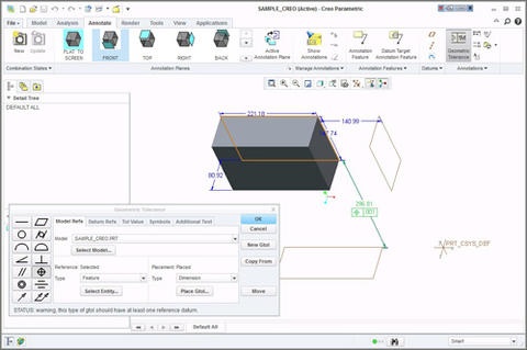
An example of this that we've seen is in ProE/Creo, which allows you to put tolerances on driving dimensions. Driving dimensions are the various dimensions defining the features which ultimately result in the final solid, but they may not necessarily be dimensions that are meaningful to the final solid. See the example below in which I've created a geomtol between the solid and a construction plane.
Ok, this is a very simple example of a feature, but the significant point is still illustrated: unless you understand the relationship between that plane and the solid (i.e. the feature, i.e. ProE's "secret sauce"), that dimension and geomtol are meaningless. This is an inherently different style of tolerancing than what is used in either UG/NX or V5, which makes standardizing the data between them difficult.
Anyway, to make a long story short, in my quest to understand a topic that confused me, I found out that there is general confusion and inconsistency on the topic . . . but people are working on it.
.png?width=450&name=AdobeStock_188705270%20(2).png)


.jpeg?width=450&name=AdobeStock_289023609%20(2).jpeg)


.jpg?width=450&name=Application%20Lifecycle%20Management%20(1).jpg)


