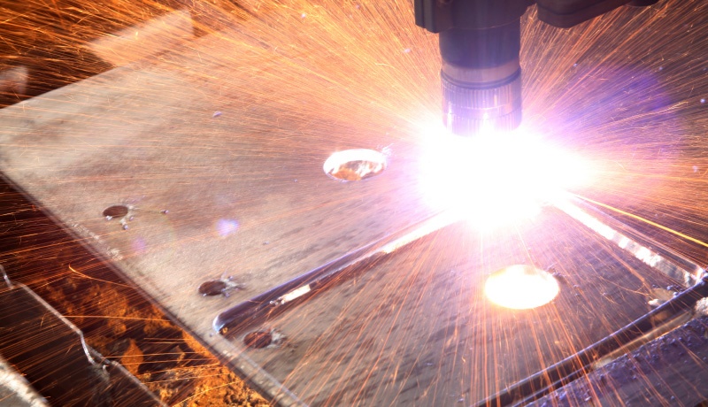
As water jet and laser cutters become more sophisticated, the geometries that they are able to cut are also increasing in complexity.
In recent years, the ability to angle cutting heads has meant that instead of being restricted to vertical cuts, bevel cuts now become possible.
From the machine programming and geometric point of view, generating the bevel information can be complex. This information then needs to be transformed into cutting head position and instructions to actually manufacture the part.
Generating the data to cut a bevel along a straight edge is the simple case; the data needed to bevel a complex curved edge is far more challenging.
Defining ‘Ruled Surfaces’
In geometric terms, the surfaces that may be cut by laser or water jet beveling cutting head are called ruled surfaces, where the surface can be swept out by moving a line in space.
If designing the part in a CAD system, we use a chamfer operation which produces a ruled surface swept out between the contact points on the support surfaces.
Simple cases are planar cuts where the head moves along a straight line or a cylindrical cut where the head moves along an arc. If we angle the head toe bevel these edges, the resulting movements become a plane at an angle or a conical surface respectively.
The more general chamfering operation allows the use of an arbitrary curve to generate the ruled surface.
Beveling A D Shape: An Example Using a Bevel Cutting Laser
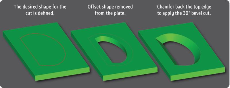
To illustrate this discussion, consider a case where we want to make a bevel cut on the letter D created in a 10 mm thick plate.
The vertical section is straight and the curved section is a general curve described by a spline.
We are going to cut the chamfer (bevel) at an angle of 30° relative to the vertical from the D shape at the top of the plate.
Adopt the Processes Needed to Sell More Machine Tools
Read Our Free eBook!
Step 1 - Defining the Shape for the Cut
One method is to define the shape in a CAD system to make a vertical cut in the shape of the D and chamfer at an angle of 30° with a width of 10/cos(30°)mm.
Using this method makes the required D shape but on the bottom face of the plate, so an offset to the original shape is needed before the vertical cut.
The 30° chamfer is then applied to the D shape.
There are alternative ways of specifying the chamfer.
For example, the Spatial CGM modeling kernel provides a hold-curve chamfer which allows the user to specify the curve and face as the inputs to create the ruled surface.
This capability would not have required the extra offset step in this construction.
Step 2 – Defining the Cutting Path for the Head
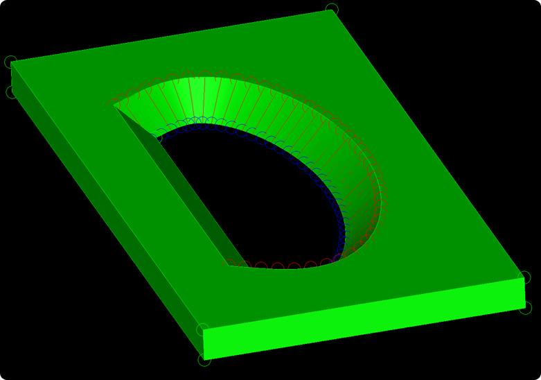
The cutting path should start at an arbitrary point on the upper curve and end at the single corresponding point on the lower curve that can be connected to the upper point by a straight line that lies on the surface.
As it is a ruled surface, there is always a corresponding point by construction.
The resulting head movement is defined so that the entry point follows the upper curve, and the exit follows the lower curve with the line joining these remaining on the ruled surface.
As the head steps along each entry point defining the top curve, if the exit point is not correctly incremented along the bottom curve, then either too little or too much material will be cut away, resulting in the bevel not being smooth.
In geometric modeling kernels the surfaces are generally parametric.
A parametric surface maps a rectangle defined within a 2D real vector space (called parameter space) into a 3D real vector space (often called object space).
For the ruled surfaces generated by the chamfer, one of these parameters is constant along the ruled line.
In other words, if the u and v parameter values at the entry point are known along with the u parameter at the exit, then the v parameter value needed at the exit is the same as the v parameter value at the entry, simplifying the calculation of the exit point.
For More on How Manufacturers Are Leveraging CAD Data
- Design and Manufacture Move Closer Together
- The Impact of Model-Based Definition on 3D Modeling & Manufacturing
- How Poor 3D Data Translation Can Derail Project Timelines and Costs
Conclusion
Using the chamfer operation in a modeling kernel provides a way to describe a ruled surface that provides a beveled cut for a specified shape.
The geometric parameters of this surface can be used to generate a series of entry and exit points for cutting such a shape.
Together with the knowledge of the machine’s accuracy and positioning abilities, this method provides an accurate way to generate an algorithm to calculate a cutting program for a laser or water jet cutter.


.jpg?width=450&name=Application%20Lifecycle%20Management%20(1).jpg)


