

As we live in a less than perfect world, 3D CAD models are far from perfect. Particularly, models often times contain gaps, which can be found between adjacent vertices, edges, and faces.
When gaps are tiny, they may not cause problems. You may not even be aware of their existence. Good tessellators are able to produce watertight meshes and robust operators are able to carve out desired features. However, once the gap size exceeds your modeler’s tolerance, they become uncontrollable. Most of the downstream operators such as Boolean or Offset will either fail in the middle or finish with an unusable model.
So how do you go about finding those problematic gaps? In CGM, we use the checker. This tool reports, by default, all the gaps which have a size bigger than 100 times the model resolution. The model resolution is the minimum length CGM can represent. For example, if the distance between two points is less than this value, the two points will be treated as identical. CGM trusts the robustness of its downstream operators and requires the operators to function well with the gaps under 100 times this size.
Once you know the model gap anomaly, you can use the CGM healing tool to repair it. This tool provides two techniques for you to choose from:
Technique One
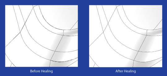
The first technique heals a gap by extending and computing the intersections of the surfaces or curves around the gap. It works nicely for simple gaps (e.g. gaps lie on planar geometries), but might not be optimal in complicated cases. This technique will keep your model intact and will not make any shape changes.
Technique Two
For the more complicated cases, you might want to apply this second option. This technique deforms the surfaces or edges around a gap and computes the intersections if necessary. The deformation in this approach does change the model shape. The tolerance values will need to be set to limit the maximum change. This healing tool works both globally or locally and can be used to automatically heal all the gaps in a model, or heal the gaps only in a selected area. This local technique will keep the rest areas of the model untouched (You can get the gap location info from the checker tool).
Cracks vs Gaps
There are people who claim they have models with large gaps, however those noticeable gaps on a display screen are not gaps, by definition. They are “cracks”, as we call them. We define a crack to be an open area surrounded by edges or vertices which are not topologically connected. For example two faces can be very close to each other on two boundaries, but they may not be topologically adjacent. In other words, the model does not know the two faces are connected over the boundaries.
How to Heal Cracks
CGM also has a tool, called the assembler, which can be used to heal cracks. This tool does not directly heal the cracks; instead it converts the cracks into gaps. It loops through all the cracks, calculates their sizes and compares them with a tolerance value. If a crack has a size less than the tolerance, the topology connection link will be established on the edges or vertices around the crack and thus the crack changes to a gap. Now the model is repairable.
What About This Tolerance Value?
How do you choose the value? Before you come up with a value, consider the model has a hole, which is a feature you don’t want to remove from the model. You might have already noticed a hole could be a crack too, a big crack by definition. So the tolerance value should be larger than the largest crack you want to heal and smaller than the smallest hole you want to keep.
These powerful tools are necessary for 3D geometric modeling. 3D CAD models are created in many different systems, with many different techniques and do not always produce perfect results. Having these tools help move us a little closer to the desired results.
.png?width=450&name=AdobeStock_188705270%20(2).png)


.jpg?width=450&name=Application%20Lifecycle%20Management%20(1).jpg)


