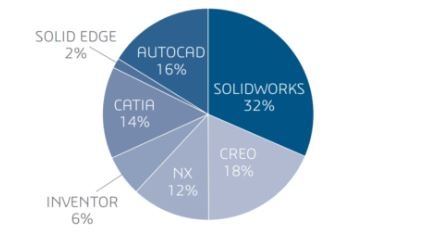
Since launching in 1995, SolidWorks has emerged as a widely adopted computer aided design (CAD) and computer aided engineering (CAE) suite. In fact, as of March 2016 SolidWorks had captured 32% of the CAD market, making it the leading CAD suite in use.
The Computer Aided Design (CAD) Market in 2016
Source: SolidWorks
This is not surprising. SolidWorks is a robust and highly versatile CAD suite, one that not only enables engineering and design teams to readily design, analyse and document their work, but to manage it against different product development issues relatively seamlessly.
One example of this aspect is the availability of both SLDPRT (short for SolidWorks Part) and SLDASM (short for SolidWorks Assembly). This article examines how the differences between SLDPRT and SLDASM have made product development processes efficient.
What is SolidWorks?
As stated earlier, SolidWorks is a CAD suite. In 2016, SolidWorks had been adopted by more than 200,000 companies in 80 countries, registering over three million individual users. Thanks to its widespread market adoption, SolidWorks is effectively a mainstay CAD suite that software application developers and 3D printing hardware makers should support.
Besides strong adoption in the market, SolidWorks is a powerful CAD suite with comprehensive design and analysis features. Its users consider SolidWorks to be relatively easy to learn, be it for students or even engineering/design teams pivoting from competing CAD suites.
However, SolidWorks’ built-in simulation, visualization, product data management and technical communication functions enable engineering teams to consolidate most core design work to just a single suite instead of disparate software. This helps make the design process more efficient, but with the parallel upside of controlling costs and streamlining software licenses.
Source: SolidWorks
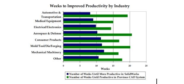
Given how SolidWorks leverages these strengths, it is not surprising that it has emerged as the leading CAD solution in use in the additive manufacturing industry. Its users, which include firms in the aerospace/defence, medical and automotive industries, consistently report improvements in productivity and time-to-market following their adoption of SolidWorks.
What is SLDPRT?
SLDPRT is one of SolidWorks’ native file formats. As the name suggests, SLDPRT is the format utilized to design and view specific parts of an overall system.
This is because engineers usually design complete systems with manufacturability in mind, so each part or component of a system is designed and analysed individually. SolidWorks’ product data management feature lets teams to access and store the design files for individual parts.
SLDPRT also offers other advantages. For example, an original design firm could protect its IP by just sharing an individual part (i.e. one SLDPRT) file to an external party, such as a client or supply-chain partner, without having to share the full design.
If the receiving party’s software is equipped to read SLDPRT (which is possible if applications use tools such as 3D InterOp), they can examine the specific part in full-fidelity without needing the fully integrated design. In other words, the receiving party does not necessarily need SolidWorks.
What is a SLDASM File?
Optionally, SolidWorks also enables its end-users to combine multiple SLDPRT files into a single file with the SLDASM extension. Instead of individually printing a system’s parts (via many SLDPRT files), you could use a single SLDASM file to print the complete system.
SLDASM could be advantageous where a CAD project simply has too many individual parts to manage. In this case, revising individual parts could result in inefficiencies (e.g. hours spent) in individual modifications and documenting changes for the original designer.
Likewise, external supply chain partners, vendors and/or clients might prefer the SLDASM over a collection of SLDPRT files for cost-control purposes. It is a consolidated asset. Moreover, the revision process could be easier as the overall system’s constraints are accounted for (whereas focusing on a single SLDPRT in isolation could risk disturbing the overall system).
You could say that SLDPRT and SLDASM work in tandem. Engineers will undertake the initial design work with SLDPRT (i.e. focus on each part individually), while downstream parties (e.g. the manufacturer) could use the SLDASM to produce and test the product (for quality, etc).
See Our FREE EBook on How SDKs Help Develop Future Proof 3D Software for 3D Printing Companies
Download
Let Your Applications Read SolidWorks with 3D InterOp
With SolidWorks firmly in place as the most adopted CAD suite, it is clear that the wider additive manufacturing industry requires solutions to manage the glut of SLDPRT and SLDASM files.
For example, 3D printing manufacturers must have printing hardware that is interoperable with the SolidWorks CAD environments of their original design partners. Likewise, two design firms that have partnered on a single project (which is common in the defence industry) might utilize two different CAD environments, e.g. one on SolidWorks and another on CATIA.
You can bridge these gaps through solid interoperability solutions in the form of software. Spatial’s 3D InterOp is a software development kit (SDK) available to software application developers and hardware companies servicing the additive manufacturing industry.
The 3D InterOp SDK enables you to equip your applications to fully read all SolidWorks files, not just SLDPRT and SLDASM, but SLDDRW (SolidWorks Draw File) as well. Be it the SLDPRT or SLDASM file’s surface geometry, metadata, color, texture or other design aspects, you can build a SLDPRT and SLDASM file viewer capability for non-SolidWorks environments.
Furthermore, our SDK will also let your applications read CATIA, Autodesk Inventor, Solid Edge and NX files, providing your end-users the ability to collaborate with all engineering workflows.
Examine how 3D InterOp will equip your application to support today’s additive manufacturing industry needs by requesting an evaluation today.



.jpg?width=450&name=Application%20Lifecycle%20Management%20(1).jpg)


