

2021 1.0.1 Enables Collaborative BIM and CAD Workflows, New Functionalities for Metal 3D Printing and Sheet-Metal Manufacturing, and More
Release Highlights:
- Unite Architectural Form and Engineering Function: Spatial Offers One-Stop Components for Collaborative BIM Workflows
- Accelerate 3D Printing: Automated Lightweighting and Support-Creation with CGM Modeler
- Fast Sheet-Metal Manufacturing: Quickly Detect Bends and Unfold Parts with CGM Modeler
- Find Your Way Around Tessellated Geometry: Spatial Now Supports Canonic Edge and Face Recognition in Polyhedral Models
- Enable CAD Workflows in Parallel: Quickly Reconcile Multiple Design Changes to the Same Model with Entity Comparison in the 3D ACIS Modeler
- Let the 3D ACIS Modeler Quickly Simplify Your CAD: New Multi-Threaded and Canonical-to-Canonical Simplifications at Your Service
- Other Highlights in 2021 1.0.1
 Unite Architectural Form and Engineering Function:
Spatial Offers One-Stop Components for Collaborative BIM Workflows
On-going advances in software permit increasing integration of architectural and engineering workflows to extend the traditional functionality of BIM applications. As a result, architects and engineers can more easily collaborate virtually to optimize architectural form and engineering function — while changes are still easy and before any expensive procurement and construction begin.
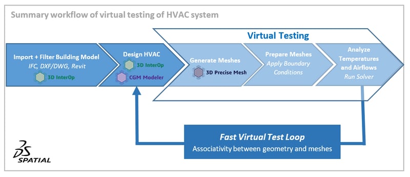
Consider the layout of a heating, ventilation, and air-conditioning (HVAC) system for a building. Initial designs for complicated systems like HVAC sometimes do not function as originally intended – especially if architectural changes to the building are made. To solve this issue, one can conduct virtual “trial and error” tests of the performance of HVAC designs. In doing so, engineers can flexibly test designs early and thus minimize project risk.
1. Import and Filter IFC Building Model with 3D InterOp
 |
| Import and filter IFC model of building |
Spatial's 3D InterOp suite of translators enable a key first step in the collaboration between architects and engineers by importing a variety of BIM formats. These formats range from standards like IFC to commercial formats such as DXF/DWG and packages like Revit. For example, BIM applications can quickly import complex IFC models of office buildings with many stories, each story containing various structural elements (walls, columns, floors, doors, windows) as well as mechanical and electrical systems.
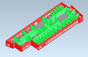 |
| Filter specific story of IFC file to only show structural elements like walls, windows, and doors |
3D InterOp now enables the activation of filters to only import specific information contained in an IFC file. For example, applications can filter IFC models for specific stories and structural elements as well as associated data for electrical, water, fire-suppression and heating, ventilation, air-conditioning (HVAC) systems. Applications enabled by 3D InterOp can directly access only those specific subsets of data needed in an IFC file, which are relevant for downstream workflows.
With the option of upstream filtering in 3D InterOp, architects and engineers can more efficiently leverage specific information in complex models. Such flexibility greatly enhances applications' productivity – especially for large projects with many levels of embedded data.
2: Design HVAC System with CGM Modeler
Assume that a specific floor of the office building does not yet have an HVAC system. To design an HVAC system for a specific floor, an engineer must add relevant components like ducts, vents, blowers, pipes, pumps, and heat-exchangers to the architectural model.
Both 3D InterOp and CGM Modeler can be employed by a BIM application to quickly design an HVAC system. For example, 3D InterOp allows the import of models for blowers, valves, pumps, compressors, and heat-exchanges in a variety of standard CAD formats such as IGS, STP, and JT as well as commercial packages like SolidWorks, CATIA, NX, Inventor, and Creo. In addition, CGM Modeler enables the creation of commands to automate the task of creating repetitive HVAC components such as ducts, vents, and pipes into the architectural model. As a result, engineers can quickly integrate HVAC components into one design in an existing architectural model.
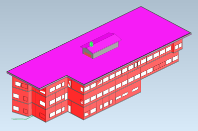
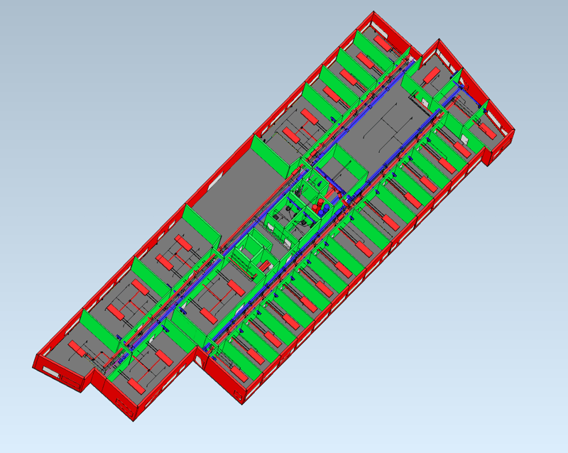 Finished HVAC design for 3rd floor
3. Virtual Testing: Create Mesh with 3D Precise Mesh
Consider a hot summer day in the afternoon. Will the newly-designed HVAC system cool rooms to comfortable temperatures for employees while also conserving energy costs? To answer questions such as this, the engineer can conduct a computational fluid-dynamics (CFD) analysis to determine the temperatures and airflow in rooms with the HVAC system turned on during a hot summer day.
The first step in conducting such a CFD analysis within a BIM application requires meshing of rooms, enabled by 3D Precise Mesh from Spatial. The meshes can include not only structural elements like walls, windows, and doors but also specific components like ducts, vents, pipes, and radiators for HVAC systems, and even furniture and office equipment for more detailed analyses.
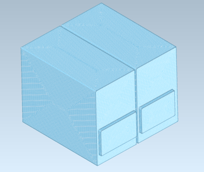 |
| Volume Mesh of Rooms for CFD Analysis |
The process of creating volume meshes from room geometry for a CFD analysis can be a challenge – especially if details such as components and furniture are considered. However, 3D Precise Mesh enables robust and high-quality meshing capabilities that make this task easier.
For example, 3D Precise Mesh automatically creates surface meshes that respect the internal surfaces of rooms depending on detail: simpler for just structural elements to more complex for components, office equipment, and furniture. From the surface meshes, 3D Precise Mesh then creates volume meshes of the rooms’ interiors. This two-step process is more robust than simply creating a volume mesh.
Furthermore, 3D Precise Mesh enables associativity between the meshes and underlying geometry. The application can automatically incorporate any design changes made to the architectural model or the HVAC system into the meshes. As a result, architects and engineers can quickly iterate design changes to geometry without the need to manually update meshes each time.
The meshing process can be guided by various options embedded in 3D Precise Mesh that allow applications to quickly clean geometry and ensure that the resulting volume meshes are watertight. In doing so, 3D Precise Mesh enables the quick creation of quality meshes with as much geometric detail as necessary.
In addition, meshes created with 3D Precise Mesh can be fine-tuned to account for specific cases such as high-speed flows. High-speed flows in rooms might occur where duct outlets from the HVAC system are present. In such cases, 3D Precise Mesh now enables the automatic creation of tunable boundary-layer meshes to obtain more accurate results.
4. Virtual Testing: Prepare Mesh
Once the volume meshes of rooms have been created, the engineer adds boundary conditions to the meshes. The boundary conditions can be in the form of internal wall temperatures, inflow/outflow rates for vents and water lines, airflows through open doors and windows or leakage around closed doors and windows, solar loading from windows, and any internal heat-sources such as employees or office equipment like computers.
5. Virtual Testing: Run Solver and Analyze Results
Now, the engineer is ready to virtually determine if the initial design of the HVAC system can efficiently handle a hot day. The engineer directs a CFD solver embedded in the BIM application to calculate temperatures and airflows within the rooms at different times. The engineer can analyze the results to determine if any modifications to the HVAC system or rooms’ architectural configurations are necessary.
Thanks to associativity between the meshes and underlying geometry, with any design changes to the architectural model or HVAC system made, the meshes can be automatically updated, and a new simulation conducted quickly. After one or more such design iterations, an optimal layout for an HVAC system can be achieved before the expensive construction begins and any design changes become increasingly difficult.
Spatial’s suite of 3D InterOp translators and 3D Precise Mesh meshing components enable multi-role teams of architects, interior designers, supply-chain purchasers, engineers, and technicians to collaboratively work together and conduct “trial and error” tests of designs.

Click to learn more about 3D InterOp, CGM Modeler, and 3D Precise Mesh.

Accelerate 3D Printing:
Automated Lightweighting and Support-Creation with CGM Modeler
Digital design allows engineers to optimize virtual parts not only for in-service performance — weight, reliability, appearance — but also for manufacturability and ultimately cost. Parts intended for 3D printing offer new design opportunities previously unobtainable by traditional subtractive manufacturing methods and are particularly ideal for virtual optimization.
Spatial’s CGM Modeler allows software applications for 3D printing to automate the virtual optimization of parts for both service and manufacturability. In particular, Spatial enables not only the “lightweighting” of parts but also the creation of supports during printing.
With functionality embedded in CGM Modeler, developers can quickly write user-friendly 3D printing applications that quickly eliminate unnecessary material yet still maintain necessary stiffness by hollowing solid volumes and adding stress-bearing patterns such as ribs, buttresses, and even complex lattices.
1. Import Part: Normal Quick-Release Lever for Bicycle Wheel
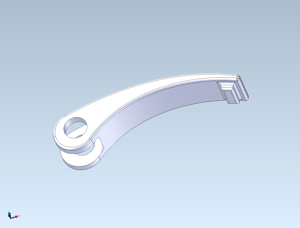 |
| Normal quick-release bicycle lever for commuter bicycle |
Consider the example of the CAD model of a quick-release lever for the wheel of a normal commuter bicycle, which was imported by 3D InterOp. The lever is solid because weight is not really important. The important attributes for this part are cost, ease-of-use, and robustness. As a result, the lever is simply designed and can be die-cast from solid steel or aluminum blanks and then machined.
2. Optimize Part by Lightweighting: Create Internal Honeycomb Shell
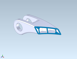 |
| Super optimized “lightweighted” bicycle lever with a shelled honeycomb lattice |
However, consider a fancy high-end touring bicycle and a very picky professional racing team as a customer. For such a racing team, weight is paramount. Hence, the quick-release lever must be as light as possible but also functional and certainly robust. What to do?
3D metal printing provides the answer. 3D printing allows the manufacture of lightweight, stiff parts, which are impossible to make with traditional manufacturing methods. For a quick-release lever for professional racers, the original lever can be optimized by creating a shell structure with an internal honeycomb lattice to eliminate weight while preserving stiffness and ultimately robustness.
With the aid of CGM Modeler’s various modeling operators, a honeycomb structure is quickly created and trimmed with the external surfaces of the original lever. Then the original lever is shelled to the desired thickness and subsequently united with the trimmed honeycomb structure. Now we have a lightweight yet stiff lever custom-designed for a professional racing team.
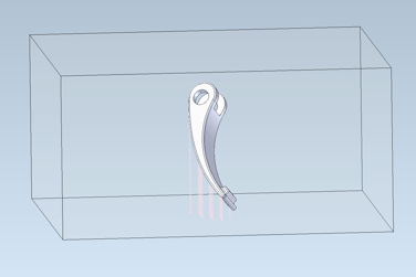
3. Orient Part for 3D Printing
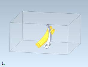 |
| Orient lightweighted lever with CGM Modeler for 3D printing (oriented lever highlighted) |
After the lever is optimized by lightweighting, it can be oriented on a virtual tray for 3D printing. CGM Modeler enables an application to select an appropriate orientation for the user depending on various user-controlled geometric options to minimize support material.
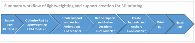
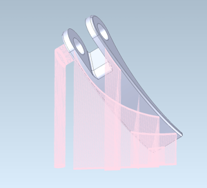
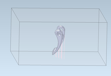
4. Create Perforation Patterns and Supports and Anchors for 3D Printing
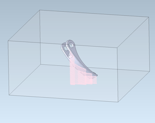 |
| Supports created by the CGM Modeler for the lightweighted lever |
Now, users of the 3D printing application are ready to start the CGM Modeler-enabled process of creating supports to hold the lightweighted lever during printing. The supports not only secure the part but also ensure adequate heat-transfer to minimize thermal warping while ensuring easy detachment and deburring after printing. Supports, both simple and angled, with a variety of perforation patterns and attachment methodologies, are easily created with the aid of CGM Modeler’s new support operators.
 |
| Supports created by the CGM Modeler for the lightweighted lever |
First patterns for supports and anchors are created with CGM Modeler. In this example, only one pattern is created for all supports and anchors. However, numerous support patterns can be created depending on individual supports and anchors to aid in heat-transfer and detachment. Secondly, several attachment locations on the bicycle lever are defined by CGM Modeler. Thirdly, CGM Modeler creates a series of simple and knee supports and anchors between the bicycle lever and a holding tray beneath the part. These supports and anchors will hold the part during printing while conducting heat away from the part to prevent any warping.
5-6: Print and Finish Part
Now the optimized lever is ready for printing with stiffness maintained and adequate supports and anchors defined. After printing, the supports can be easily removed, and the lever finished (e.g., deburred). It is then ready for use. We wish your racing-team customer much success with the new high-performance, lightweighted, quick-release lever!

Click for more information on CGM Modeler.
Fast Sheet-Metal Manufacturing:
Quickly Detect Bends and Unfold Parts with CGM Modeler from Spatial
Sheet-metal is often the obvious choice for a myriad of industrial uses, ranging from brackets and enclosures to ducting and car bodies. An important element of sheet-metal manufacturing is the ability to virtually reverse the design process to unfold CAD parts and lay the original sheet-metal flat. Features can then be removed, and the exact size of the sheet-metal blank can be determined and optimally nested within standard sheets for automatic cutting.
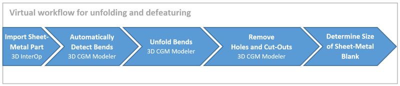
The entire workflow for sheet-metal parts, from the detection of bends and virtual unbending to defeaturing, can be implemented into any CAD-CAM software-application with Spatial’s powerful CGM Modeler.
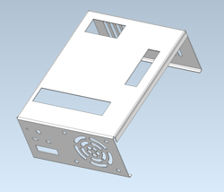 |
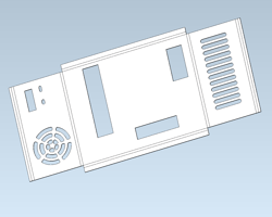
| Desktop computer housing manufactured from sheet-metal |
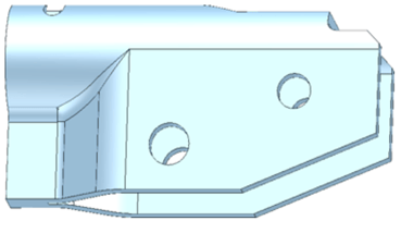
1. Import Part: Sheet-Metal Housing for Desktop Computer
Consider for example, the sheet-metal housing of a desktop computer. The housing contains various holes and other cutouts for electrical connections and cooling.
2. Automatically Detect Bends
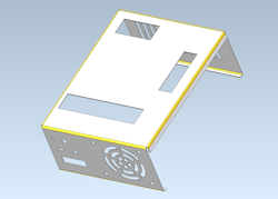 |
| Cylindrical bends of computer housing detected by CGM Modeler |
CGM Modeler begins the process of unbending and defeaturing the housing by automatically detecting cylindrical bends in the model. Various options control the bend-detection process to provide the application utmost flexibility. After the bends are detected, bend objects are created, and the application can interrogate each bend for geometric properties, including type (cylindrical or conical), radii (minimum and maximum), and bend angles.
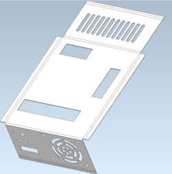 |
| Unbending mid-process: several bends unfolded |
3. Unfold Bends
After CGM Modeler detects the bends, the housing is ready to be unfolded. Additional functionality in CGM Modeler in the form of an unbend operator sequentially unfolds each detected bend. Several optional parameters in the operator control the unbend process.
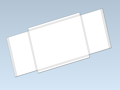
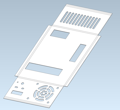 |
| Unbending completed process: all bends unfolded |
 |
| Feature removal mid-process: holes removed |
4. Remove Holes and Cut-Outs
After the computer housing has been unfolded, CGM Modeler removes holes and other cut-outs to obtain the original sheet-metal blank. The process of removing such features follows a similar process to unbending. First, the holes and cut-outs are detected by feature-detection functionality embedded in CGM Modeler. Then the holes and cut-outs are removed sequentially, leaving just the external perimeter of the original unfolded housing.
 |
| Feature removal completed process: all features removed (holes and cut-outs) |
 |
| Sheet-metal blank overlayed on unfolded/defeatured computer housing |
5. Determine the Size of the Sheet-Metal Blank
After all the holes and cut-outs have been removed, CGM Modeler can be used to determine the size of the sheet-metal blank required to manufacture the computer housing. A bounding box is created from the external perimeter of the unfolded and defeatured housing. This bounding box determines the minimum size of the sheet-metal blank. After the blank's size is determined, the application can orient and nest this and other unfolded/defeatured designs onto standard sheet-metal rolls for automated cutting.
Click to learn more about CGM Modeler.

Find Your Way Around Tessellated Geometry:
Spatial Now Supports Canonical Edge and Face Recognition in Polyhedral Models
Traditional boundary-representation (BREP) models for CAD geometry are ubiquitous throughout the CAD industry and are noted for their preciseness. However, sometimes such preciseness is not needed, and instead, speed is preferred. This is especially true for large models comprised of many separate parts. Furthermore, oftentimes BREP geometry is not even available – especially in downstream workflows. Instead, only tessellated geometry (e.g., STL files) is available.
Because polygonal models lack the preciseness of solid BREP models, one historic drawback of polygonal models has been the inability to robustly detect features such as canonical edges and faces in tessellated geometry. Canonical edges and faces often define important entities like holes, pockets, bosses, and bends, which must be identified by CAD/CAM applications for additional processing.
Consider a manufacturing application for the laser-cutting of sheet-metal that generates numerical-control (NC) code in order to direct the movement of laser-tipped robotic arms through 3D space. For such an application, the user virtually directs the robotic tip through all the features (usually edges of holes and through-pockets) to be cut. However, the polygonal data structure only knows a “connected bag of triangles” – how will the tool find the edges of such features in a tessellated model without precise BREP?
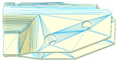 |
| Before edge detection with CGM Polyhedra |
Spatial’s CGM Polyhedra polygonal modeling engine has the answer. CGM Polyhedra now provides a “segmentation” operator that allows applications to detect canonical edges and faces in tessellated models robustly. As a result, application developers can implement the detection of high-order features such as holes, pockets, and bosses in their applications.
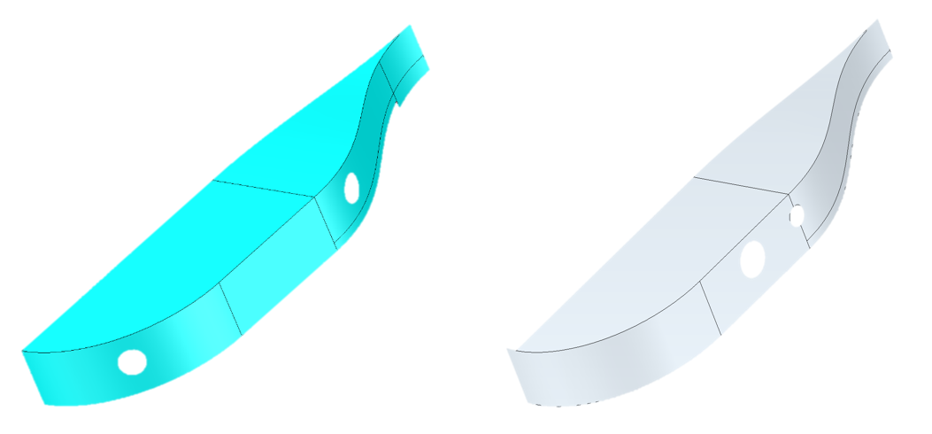
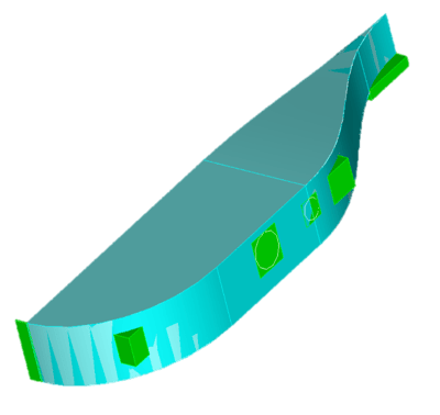
A generic example of the new segmentation operator at work are edges and holes in the tessellated model of a filleted sheet-metal flange.
 |
| After edge and face detection with CGM Polyhedra |
In this case, only triangles exist in the original polygonal model. Of course, the user can see features like straight edges and the perimeters of holes in the model, but the polygonal data-structure does not innately recognize these features.
Now consider the same polygonal model after
processing by the new segmentation operator in CGM Polyhedra. Straight and curved lines for edges, bends, and weld-fillets, as well as arcs for through-holes, are quickly detected, but the underlying original tessellated model remains untouched.
Click to learn more about CGM Polyhedra.

Enable CAD Workflows in Parallel:
Quickly Reconcile Multiple Design Changes to the Same Model with Entity Comparison in the 3D ACIS Modeler
Complex virtual engineering projects often require technical drafters and engineers to work collaboratively across multiple departments and time zones. Modern CAD applications typically allow parallel workflows. However, sometimes a multitude of designers working on different aspects of a project – say a car body – can cause problems.
For example, two drafters working on the same CAD model can create overlapping versions of the same body at different times. As a result, it can be rather difficult to reconcile design changes made by different drafters to the same model.
Spatial’s 3D ACIS Modeler now offers functionality to mitigate the effects of changes to the same model. More specifically, the 3D ACIS Modeler offers “entity comparison”- different changes to the same body in a model can be automatically visualized and quickly reconciled. This allows developers to reduce their application’s dependency on a series of Boolean operations to compute such comparisons.
As an example, consider the model of a simple design with a curved surface defined by splined edges and two holes. Imagine that this model is the beginning of a design for a car fender. In this case, two drafters have created slightly different geometry for the fender. This often occurs during design iterations for complex models in which space is tightly limited, and the model implicitly defines a highly constricted interior volume.
Two separate versions of the same model
The two versions of the same model overlap. Where exactly do the models overlap, and what geometric entities (such as faces and edges) are involved? Such information would be extremely useful in order to reconcile the two versions of the same model.

Superposed versions of same model – difficult to determine the areas of overlap
The 3D ACIS Modeler can now automatically pinpoint the regions of overlapping geometric entities with bounding-boxes, which the overlying CAD application can then highlight. In this manner, drafters and engineers in different regions can quickly visualize the overlapping regions and decide how to quickly reconcile the two different design versions, achieving one united design.
Regions of overlap identified by the 3D ACIS Modeler between two versions of the same model
Consult your Spatial team for more information on how 3D ACIS Modeler automatically removes roadblocks such as overlapping geometry from parallel design processes while saving both cost and time.

Let the 3D ACIS Modeler Quickly Simplify Your CAD:
New Multi-Threaded and Canonical-to-Canonical Simplifications at Your Service
Parametric NURBS-based geometry is ubiquitous in CAD applications and allows designers to create a myriad of 2D and 3D geometry, going beyond possible canonical forms defined by closed-form equations alone. However, sometimes developers or users of CAD applications wish to quickly convert geometry defined by NURBS – either curves or surfaces – to simpler canonical forms. Furthermore, there is often the need to convert higher-order canonical geometry to lower-order. In both cases, such simplification typically yields less complex models with significantly lower memory footprints.
Until now, 3D ACIS Modeler has offered NURBS-to-canonical simplification, albeit single-threaded. In this release, 3D ACIS Modeler now also offers canonical-to-canonical simplification as well as multi-threaded performance for both NURBS-to-canonical and canonical-to-canonical simplification. As a result, users of CAD applications powered by the 3D ACIS Modeler can simplify many different geometry types – more quickly and robustly than ever before.
For an example of the performance gains achieved with multi-threaded simplification in 3D ACIS Modeler, consider the model of a four-valve cylinder head for an automotive engine. The model has 2569 NURBS faces. Single-threaded simplification of these faces was completed in 38 seconds, resulting in 1089 NURBS faces and 2570 simpler canonical faces (e.g., planar, cylindrical, conical, spherical, toroidal). However, multi-threaded (thread-hot) simplification yielded the same results in only 27 seconds – an improvement in speed of nearly 29%.
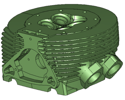
Cylinder-head with 2569 NURBS faces: multi-threaded simplification = 27s; single-threaded = 38s
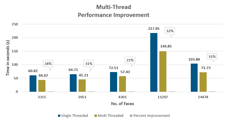
Is such performance consistent across a wide variety of models? The short answer is an emphatic yes. For models ranging in faces from 3000 to almost 15000, the speed gains varied between 21% and 32%. On average, performance gains of around 30% should be typically be expected for multi-threaded simplification. As a result, downstream users of simplified CAD models can start working sooner than ever before.
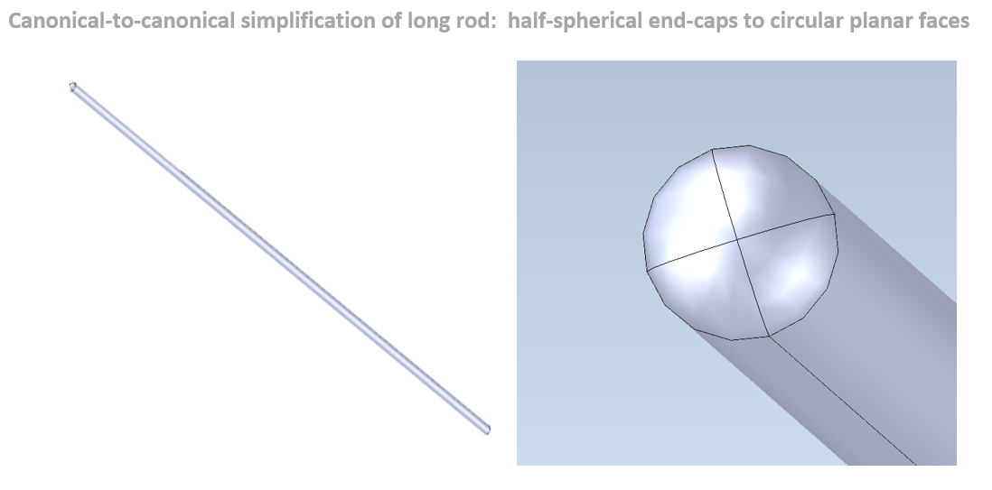
In addition to NURBS-to-canonical simplification, 3D ACIS Modeler now offers canonical-to-canonical simplification – both single- and multi-threaded. Typically such simplification occurs from higher-order to lower-order canonical geometry.
One example of this is a very long cylindrical rod with spherical caps on both ends. Because the rod is very long compared to the dimensions of its ends, the spherical caps can be treated as planar circular caps. Such a situation might arise if the tolerances of the heights of the end-caps allow simplification to planar caps. Another situation might occur during the building of scenes in an application for virtual reality, in which the detail provided by the spherical end-caps is unneeded. In both cases, 3D ACIS Modeler can simplify the caps from half-spheres to circular planar faces.
See for yourself the new enhanced capabilities of the 3D ACIS Modeler to simplify geometry as needed. Contact your account manager for details.
Other Highlights in 2021 1.0.1
3D InterOp:
- Support of multiple levels-of-detail (LODs) during JT import and support of visual materials properties during COLLADA, FBX, OBJ, and JT import
- Extraction of hole patterns from SOLIDWORKS
- Enhancements to reading DXF/DWG drawings
- Extraction of faceted BREP data as visualization from STEP and controls to tune the tessellation of BREP formats via chordal deviation for CGM
Refer to the 3D InterOp Release Notes for a complete list of updates
CGM Modeler:
- Feature recognition supports recognition of tapered holes
- Performance improvements to the flattening of imported assemblies
Refer to the CGM Modeler release notes for a complete list of updates
3D ACIS Modeler:
- Enable fast visualization refreshing of edited models with incremental faceting support
- Improvements to the detection of chamfers
Refer to the 3D ACIS Modeler release notes for a complete list of updates
3D Precise Mesh:
- Improvements to boundary-layer meshing: extension to non-manifold edges and enhancement of size-control capabilities per sub-domains
- Improvement of surface meshing from discrete CAD data
- Extension of full-patch independence to hyper-patch boundaries


