
Release 2022 1.0.1 Implements Data Reuse for BIM & AEC Applications, Enables the Reconstruction of Meshes, Improves the Efficiency of Uniting 2D & 3D Bodies, and More
Release Highlights:
Seamless BIM Workflows in AEC Applications: 3D InterOp Adds Writing IFC Data
The ability to read and write IFC data for BIM workflows in AEC applications is key to ensuring seamless data transfer from project conception to realization. The IFC format promotes efficient collaboration and coordination among increasingly globally-distributed teams and applications in AEC-centric markets.
1. BIM Workflows and Levels of Digital Collaboration
BIM workflows that utilize IFC data in AEC applications range widely from simple to complex with a variety of end-goals. As a result, such workflows are characterized by four fundamental levels of digital data usage according to the amount of collaboration.
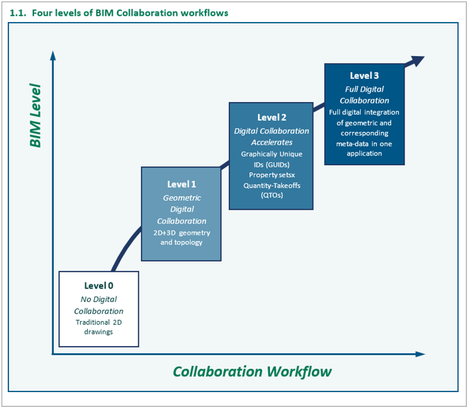
Level 0
At Level 0, there is no digital collaboration. A typical example is the use of traditional 2D paper drawings. Surprisingly such paper drawings are still ubiquitous in some domains like construction.
At Level 0, IFC data files play no relevant role.
Level 1
Actual digital collaboration in BIM workflows begins at Level 1. At this level, geometry and associated topology for construction elements as well as ancillary MEP (Mechanical, Electrical, Plumbing) systems are exchanged between AEC applications. This level makes only geometry and object definitions available for downstream workflows.
IFC data starts to play a significant role at this level, particularly in those classes that describe construction elements (e.g., IfcStorey or IfcWall) or MEP systems (e.g., IfcFlowSegment).
Level 2
Level 2 increases digital collaboration. At this level, GUIDs (Graphical User Identifier), property sets, and any QTO (Quality Take-Off) data are transferred along with geometric data. As a result, downstream workflows are more comprehensive because links between upstream and downstream geometric operations are maintained.
At this level, IFC data files can be used to identify and cross-reference objects and building-specific meta-data such as persistent GUIDs, properties, and QTOs.
Level 3
Level 3 is the most comprehensive level of digital collaboration and involves the full integration of geometry for both construction elements and ancillary MEP systems as well as corresponding meta-data for GUIDs, property sets, and QTOs – all in one application. As a result, all types of BIM data are available in one database, allowing full collaboration among all BIM stakeholders.
3D InterOp Capability: Which Level Today and Tomorrow?
How are these levels pertinent to 3D InterOp? The simple answer is that 3D InterOp imports and now also exports geometric BIM data as IFC files. Such ability to write geometric IFC data and types corresponds to Level 1 collaboration. This capability of 3D InterOp streamlines interdisciplinary BIM workflows among Spatial-enabled AEC applications and allows faster time-to-realization for construction projects.
In the near future, Spatial intends to develop 3D InterOp such that it also fulfills the requirements of exporting IFC data and is required to support Level 2 collaboration.
|
Want to learn more about how Spatial SDKs can be used in the BIM industry? Follow the button below to learn how Lubansoft leverages Spatial SDKs to build a world-class 3D BIM Toolsuite.
|

2. InterOp Reads and Writes Geometric IFC Data: Illustrative Example
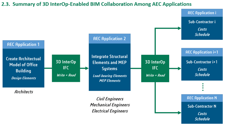
As an example of 3D InterOp’s ability to read and write geometric IFC data per Level 1 collaboration, consider the design of an office building by architects and engineers. First, imagine that a team of architects at an internationally famous architectural design firm in Switzerland creates a digital model of an office building for a project in South Korea. The model includes architectural elements like spaces, partitions, ornamental columns, stairwells, doors, façades, and windows.
After the architectural team designs the office building, a member of the team exports the model of the office building into an IFC file with Spatial’s 3D InterOp. She then sends the IFC file to a team of civil engineers at an engineering construction firm in South Korea.
The team of civil engineers in South Korea imports the IFC file into another AEC application, which uses Spatial’s 3D InterOp. The civil engineers then integrate all necessary structural elements such as foundations, load-bearing columns, walls, and slabs into the architectural model to support the building under different loading scenarios.
After the structural load-bearing elements have been integrated into the original model, an additional team of mechanical and electrical engineers subsequently integrates all necessary MEP systems into the building model.
At this point, planning and purchasing employees at the engineering construction firm can again use 3D InterOp to export models of the office building as IFC files to various sub-contractors for cost quotations and schedule estimates.
The entire BIM collaboration model, in which IFC data is transferred from application to application around the globe, is summarized in the following flowchart.
 |
The ability to transfer data seamlessly among different AEC applications, each leveraging 3D InterOp, is the key to working efficiently among globally distributed teams in an integrated BIM workflow.
This new addition to 3D InterOp will be rolled out over the next few hotfixes.
Follow the link below or contact Spatial for more information about how 3D InterOp can enable your AEC application to communicate with other applications both upstream and downstream and realize integrated BIM workflows.


Digital Reconstruction: CGM Polyhedra Enables Easy Reconstruction of Surface Meshes
Often scan data of surfaces – in the form of points, and associated normals – or surface meshes originally constructed from such scan data are imperfect in the sense that gaps and holes are present. As a result, the need arises to reconstruct new surface meshes before any value-added downstream operations such as rendering or model modification take place.
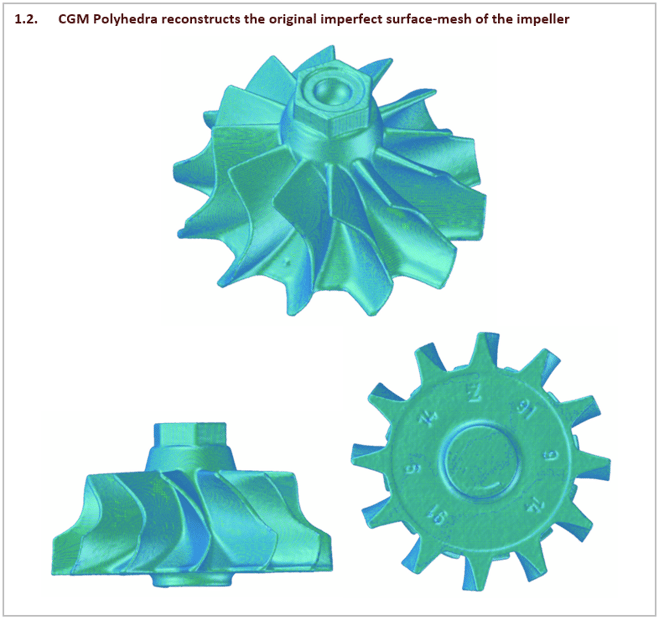
1. Reverse Engineering: Reconstruct Scan of Mechanical Part
Consider the reverse engineering of an impeller. The first step is to scan the impeller and obtain points and corresponding normal. Because the scan process is imperfect, the resulting surface mesh of the impeller has intermittent holes and gaps.
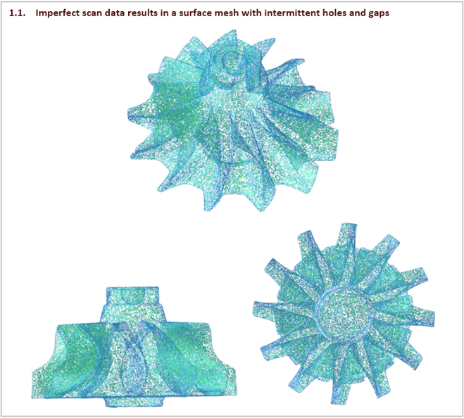
The next step is to fix the holes in the original mesh of the impeller using CGM Polyhedra. The reconstruction of the mesh results in a new mesh with all holes filled smoothly. The new mesh is now suitable for use in downstream operations.
|
Curious how you can use scan data in your BIM application? Follow the button below to learn more!
|

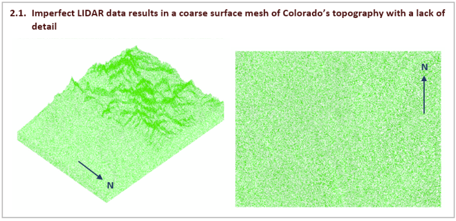
2. Terrain Modeling: Reconstruct Scan of Irregular Terrain
Another example is the terrain modeling of large geographic areas. Consider LIDAR data for a topographical map of the state of Colorado in the United States. The data is sparse, resulting in a surface mesh lacking detail. As a result, important features like mountains and valleys are difficult to recognize.
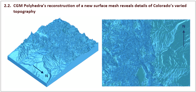
Now consider a reconstruction of the original mesh by CGM Polyhedra. The new surface mesh reveals detailed features of varied Colorado topography. The new mesh is robust and is suitable for downstream operations.
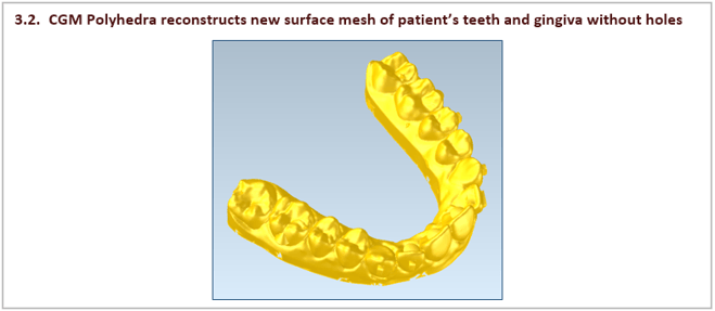
3. Digital Dentistry: Reconstruct Scan of Patient’s Jaw
Consider a common workflow from digital dentistry in which a surface mesh is created from an intraoral scan of a patient’s teeth and gingiva. The scan is imperfect with missing points. Hence, the surface mesh has many irregular holes.
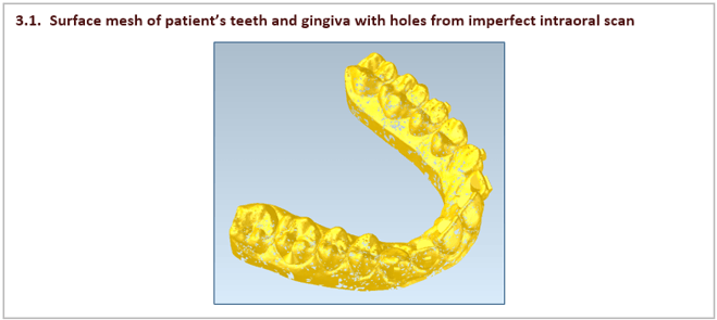
Nonetheless, CGM Polyhedra can reconstruct the original mesh into a new continuous mesh without holes. The new surface mesh not only preserves original features with detail but also ensures robust downstream operations.
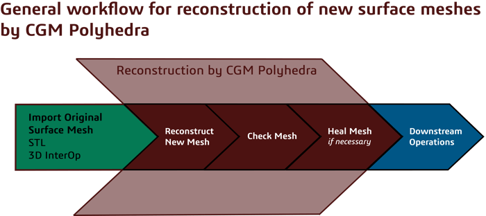
4. Reconstruction by CGM Polyhedra: Same General Workflow
In each of the three previous examples, the same general workflow with three basic steps applies as listed next and shown in the following schematic.
- A surface mesh is imported into an application – for example with Spatial’s 3D InterOp. The surface mesh has many irregular holes.
- CGM Polyhedra reconstructs a new surface mesh.
- CGM Polyhedra checks the new reconstructed mesh. If any remaining anomalies and errors are present (e.g., incorrect surface normals), then CGM Polyhedra also heals the new reconstructed mesh.
After reconstruction, the new robust surface mesh is ready for value-adding downstream operations.
CGM Polyhedra’s ability to reconstruct new surface meshes and remove holes and gaps in original meshes eliminates much tedious data preparation work. As a result, designers, engineers, and technicians can quickly concentrate on value-adding downstream operations.


N-Body-Unite: Efficient Union of Multiple Bodies in the 3D ACIS Modeler
Some specialized workflows, particularly those in the EDA industry for analysis and simulation, involve the uniting of hundreds or thousands of bodies, which can be very time-consuming. In its latest release, the 3D ACIS Modeler provides efficient approaches to uniting many bodies.
1. New Multi-Threaded 2D N-Body-Unite Function for Coplanar Sheet-Bodies: api_n_body_unite_2d
The naïve approach to perform an N-body-unite operation is to keep uniting the bodies in a sequential way, where the first body is united with the second and their output is united with the third, and forth. However, such a sequential methodology is not typically performant.
For several years, the 3D ACIS Modeler has had the capability to unite multiple bodies with api_n_body_unite. However, often EDA workflows for analysis and simulation involve a union of many 2D coplanar sheet bodies. Therefore a need arose for a new function in ACIS, which efficiently unites multiple 2D bodies. This new function, api_n_body_unite_2d, is now available in the latest release 2022 1.0.1.
Unlike the legacy n-body-unite function, the new 2D n-body-unite function is capable of using multi-threading. Multi-threading can be enabled by turning on the option thread_hot-2d_n_body_unite.
The following chart compares the timings of the legacy n-body unite versus the new 2D n-body-unite function when executed in a single-threaded mode compared to the multi-threaded mode (eight threads). For some cases where N is higher than 5000, the new api_n_body_unite_2d function is typically ten times faster than the legacy api_n_body_unite function in the single-threaded mode. Furthermore and when run in a multi-threaded mode with 8 threads, the chart shows an additional performance gain of 4-times faster.

|
Curious how you can utilize multiple threads in your 3D modeling application? Contact us to learn more and to start testing and implementing!
|

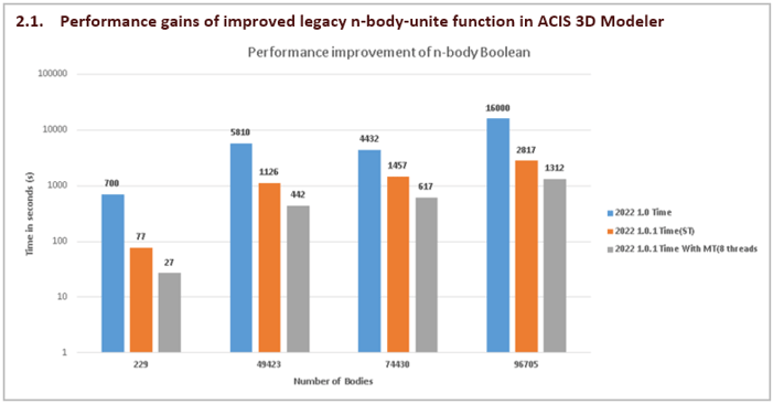
2. Improvement of Legacy N-Body-Unite Function: api_n_body_unite
In 2022 1.0.1, the algorithm behind the general n-body-unite function, api_n_body_unite, in the 3D ACIS Modeler has been redesigned to work faster and to capitalize on multi-threading.
The following chart shows the performance gains achieved by the newly improved api_n_body_unite function. Performance depends on the count of bodies participating in the unite operation and the way these bodies interact among themselves. For bodies greater than 200, a 10-fold gain in performance is observed in the single-threaded mode. After enabling the optional multi-threading mode, there are additional speed gains on the order of 3-times.
Consult Spatial today to discover how the 3D ACIS Modeler can enhance the performance of your demanding EDA application for analysis and simulation purposes with both new and improved operators for uniting multiple bodies.

Other Highlights in 2022 1.0
3D InterOp:
- New support for import of assembly model states for Autodesk® Inventor
- New capability to export FBX files
Refer to the 3D InterOp Release Notes for a complete list of updates
CGM Modeler/CGM Polyhedra:
- Additional support for 3D nesting and orientation for 3D printing applications
- Feature recognition enhancements, including tapered pockets and pads and recognition of outer-faces
- New operator to create mid-surfaces between face-pairs on solid bodies
Refer to the CGM Modeler release notes for a complete list of updates
3D ACIS Modeler:
- New ability to create convex-hulls of bodies
- Improvements to error reporting for local operations, including reasons for any failures
- ACIS-HOOPS Visualize bridge updated to HOOPS Visualize 3DF 27.00 for Windows and Linux
Refer to the 3D ACIS Modeler release notes for a complete list of updates
3D Precise Mesh:
- Major enhancements to robustness for the creation of CFD meshes
Refer to the 3D Precise Mesh release notes for a complete list of updates