
"2023 1.0.1 Expands Support for Cross-Department Collaboration, Polyhedral Modeling, Automation in Manufacturing, and More"
Release Highlights:
- Visualize More Formats With 3D InterOp
- Selectively Browse and Import Revit Views With 3D InterOp
- Improvements to Nesting in CGM Applications
- Point Cloud Alignment Improvements With CGM Modeler
- Convex Hull Generation With CGM Polyhedra
- Process Mesh Data With ACIS Polyhedra
- Checker Performance Improvements in the 3D ACIS Modeler
- Two New Sets of C++ Interfaces for 3D Precise Mesh
- Other Highlights in 2023 1.0.1
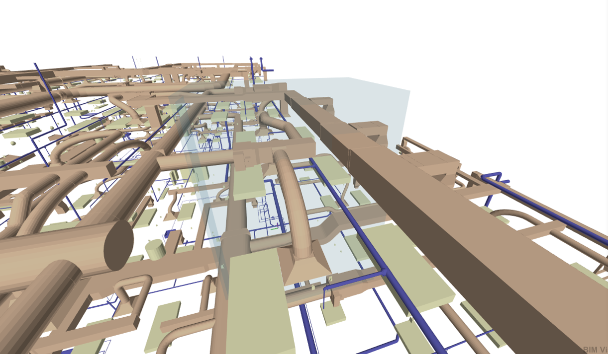
Visualize More Formats with 3D InterOp

New in 2023 1.0.1, 3D InterOp introduces capabilities to import AVEVA™ E3D Design, AVEVA™ PDMS, and Intergraph Smart® 3D formats.
Application developers working in the process industries can now extend their applications to support visualization geometry and meta-data of 3D assets. This enables plant designers and operators to build experiences on virtual twins of “as designed” or “as built” 3D assets from their design or during their operational phases. With this new ability, 3D InterOp provides application developers and end users in the process industries with more precision, control, and potential possibilities for their software and workflows.
Consult Spatial today for additional details about 3D InterOp's new capabilities and file type support, or follow the link below to learn even more about the SDK.


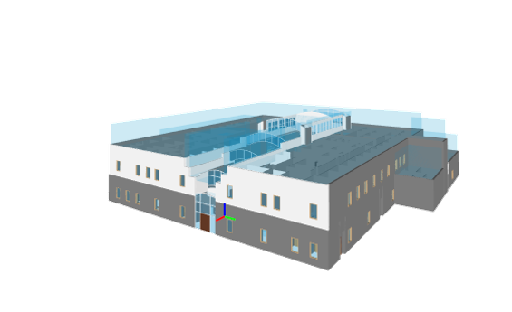
 Selectively Browse and Import Revit Views with 3D InterOp
New in 2023 1.0.1, 3D InterOp introduces capabilities to retrieve the list of views present in Revit® files. BIM and AEC Application developers can now deliver optimal collaboration experiences with Revit Views so end users can focus on specific parts of the building projects.
 |
|
 |
| Architectural View | Structure View | Mechanical Engineering and Plumbing View (MEP) |
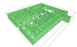
By retrieving views in a preliminary step before import, 3D InterOp enables BIM and AEC application developers to let their end users select the views to be imported into their applications. End users can load only data of interest when needed, optimizing collaboration on large projects and reducing effective import time and memory footprint in applications.
Consult Spatial today for additional details about 3D InterOp's new capabilities and file type support, or follow the link below to learn even more about the SDK.
Improvements to Nesting in CGM Applications
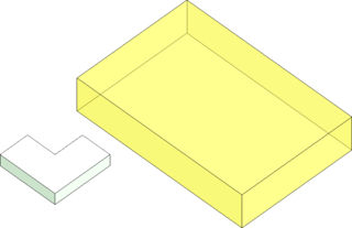
In 2023 1.0.1, nesting capabilities in CGM Modeler and CGM Polyhedra have been further improved to support contour nesting, nesting bodies within each other without interlocking, and exclusion and nesting zones.
 |
.png?width=303&height=250&name=Contour%20Nest%20Result%20with%20Disjoint%20Bounding%20Boxes%20(Default).png) |
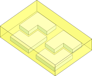 |
| Contour Nest Input Body and Tray Box | Contour Nest Result with Disjoint Bounding Boxes (Default) | Contour Nest Result with Contour Nesting Enabled |
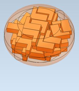
Contour Nesting, also known as 2.5D Nesting, delivers a much tighter nesting of bodies than before. With the capability to nest bodies within each other while avoiding interlock, even more parts can be nested together. All this can enable additive manufacturers to increase the number of parts per print or sheet metal manufacturers to cut more parts per sheet metal roll while delivering automation to their end users.
 |
 |
| Isometric view of the output in Optimize3D mode. | Top view of the output in Optimize3D mode. |
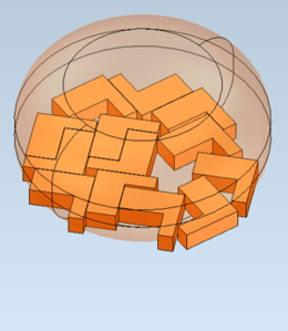
 |
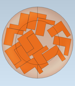
 |
| Isometric view of the output in Optimize2D mode. | Top view of the output in Optimize2D mode. |
The new exclusion zone feature enables product manufacturers to add a zone in which no result bodies will be nested. In contrast, the new nesting zone feature adds a zone that will be used for nesting the output bodies. Both of these zones enable the machine and print operators to customize their nesting area and automatically nest parts before cutting or printing.
 |
 |
| A nesting zone and an input body to nest. | Multiple instances of the input body nested in Optimize3D mode. |
 |
 |
| Multiple instances of the input body nested in Optimize2D mode. | In Optimize2D mode, the shadow of the nesting body will be used to define the nesting area. |
Refer to this technical article for specific details about CGM Modeler and CGM Polyhedra's new features.
Consult Spatial today for additional details about CGM's new capabilities, or follow the buttons below to learn more about the two SDKs.


Point Cloud Alignment Improvements with CGM Modeler
New in 2023 1.0.1, CGM Modeler introduces improvements to point cloud alignment such as:
- Fail-safety
- Careful analysis for nearly symmetric point clouds
- Option to use all points in the point cloud for a more precise alignment or down-sample them for improved performance
These new improvements can be leveraged to add more automation to manufacturing QA processes.
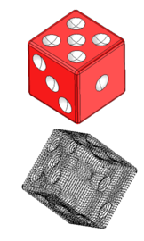 |
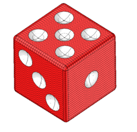 |
| Input Body and Cloud; Note Cube Has Many Near Symmetries | Output |
Consult Spatial today for additional details about CGM's new capabilities, or follow the button below to learn more about the SDK.
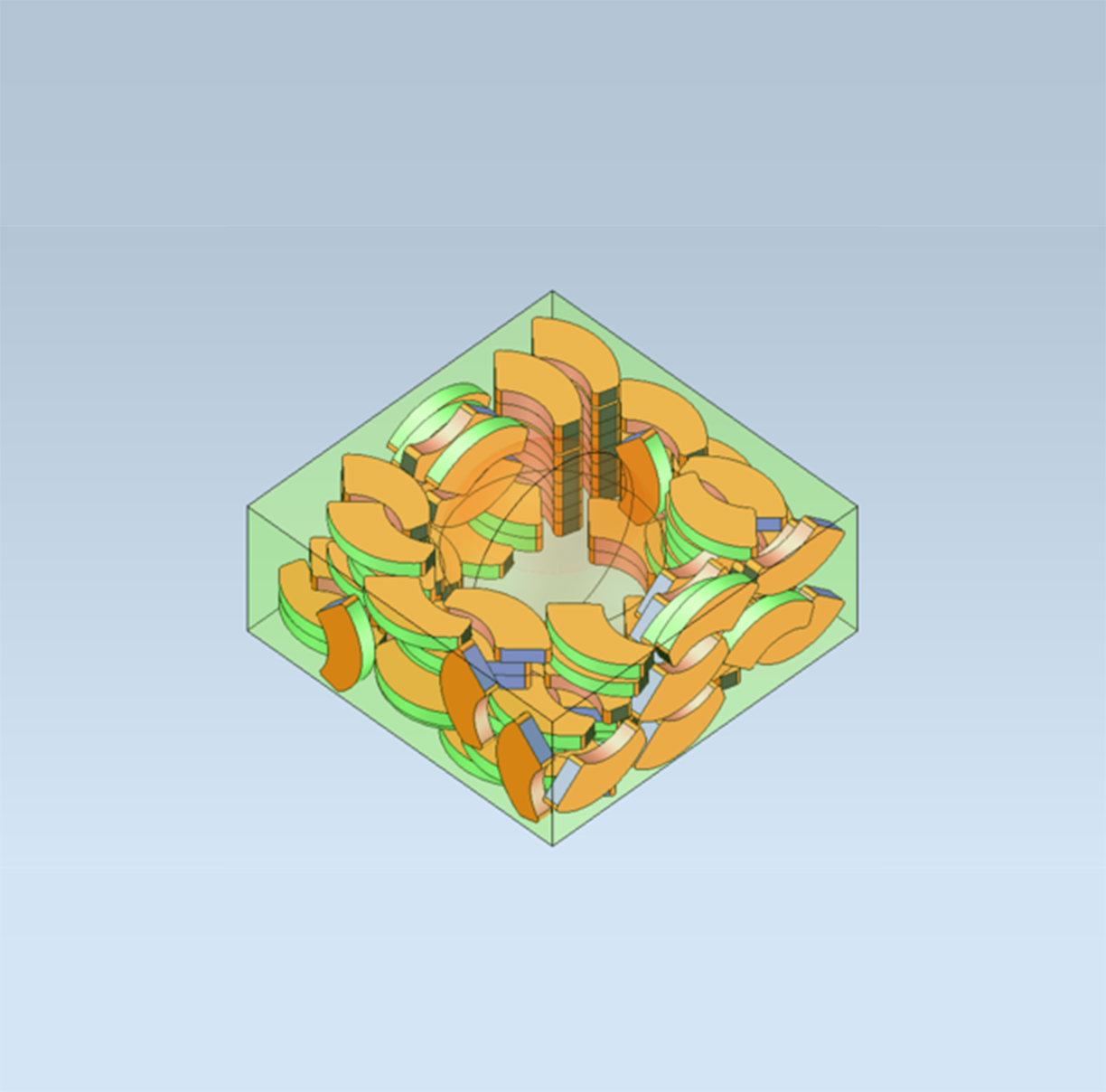
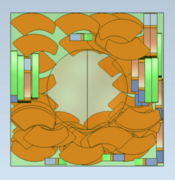
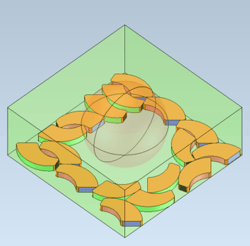
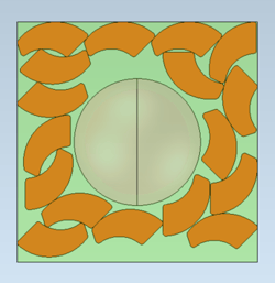
Convex Hull Generation with CGM Polyhedra

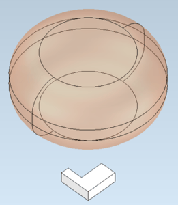
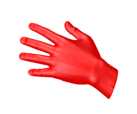
New in 2023 1.0.1, CGM Polyhedra introduces functionality for creating a mesh that represents the convex hull of a specified collection of input meshes or bodies.
 |
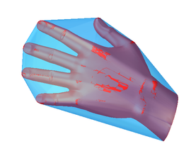 |
| Input Mesh | Output Mesh |
This can be especially helpful in robotics workflows. When detecting collisions between the robot and other objects in the 3D world, robotic software applications must check for intersections and overlaps between one subset of meshes versus another. If the input meshes are dense, i.e., there is a high number of triangles to check, the performance can be poor. To combat this challenge, applications may replace the full-fidelity meshes with simpler versions produced by CGM Polyhedra’s convex hull operator.
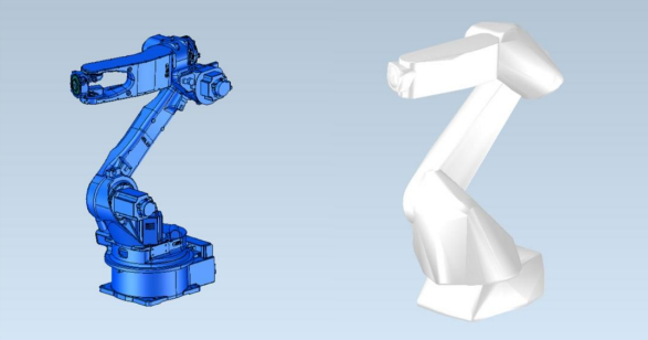 |
This results in fast collision detection. For example, a Yaskawa MH24 robot model before running the convex hull operation had 130,394 individual mesh triangles, and the resulting model, after running the convex hull, had 9,040 mesh triangles. That is a 93% reduction in triangles with minimal user intervention.
Consult Spatial today for additional details about CGM's new capabilities, or follow the buttons below to learn more about the two SDKs.

Process Mesh Data in Your ACIS Application with ACIS Polyhedra
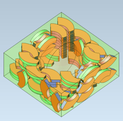
New in 2023 1.0.1, ACIS Polyhedra introduces features for segmentation, wall thickness analysis, and slicing.
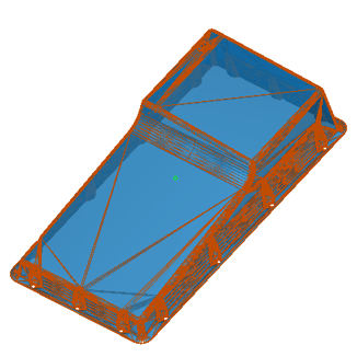 |
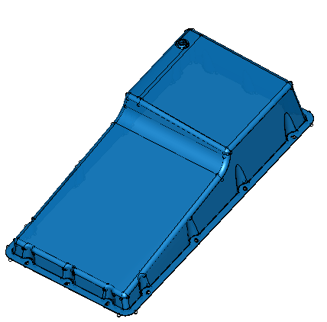 |
| Before Segmentation | After Segmentation |
With segmentation, ACIS-based applications can now introduce hard edges into a polyhedral model as well as fit canonic surfaces wherever possible. This can allow ACIS application developers to add more information and intelligence to a polyhedral model. With wall thickness analysis, additive manufacturing software developers can ensure that their application checks for printability by identifying regions that are too thin to print.
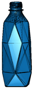 |
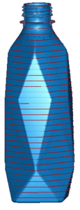 |
| Polyhedral Body | Polyhedral Body with Multiple Planar Slices |
The new slicing operation enables end users to produce bodies with multiple planar wire cross-sections from the original polyhedral body. These slices can then form the input for downstream toolpath generation modules.
These new functionalities extend the 3D ACIS Modeler further into the domain of mesh geometry and provide 3D ACIS Modeler customers with even more flexibility and performance for different types of geometric data.
Consult Spatial today for additional details about ACIS Polyhedra’s capabilities, and stay tuned for an upcoming webinar about ACIS Polyhedra early next year.


Checker Performance Improvements in the 3D ACIS Modeler
New in 2023 1.0.1, the 3D ACIS Modeler has added multi-threading support for the ACIS checker.
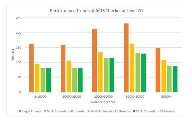
Reduced wait times are observed when checks are done at level 70, as the improper face intersection check is more performant now.
Consult Spatial today for additional details about ACIS Modeler’s capabilities, or follow the button below to learn more about the SDK.


Based on the same technology as the existing MeshGems products, these new interfaces offer access to the same industry-proven functionality with easier-to-use C++ programming interfaces.
Convergent Surface Mesher (CSM)
- Provides access to all the surface meshing functionality through a single C++ package
- Accurately drives robust surface mesh generation through simple C++ interfaces
Convergent Volume Mesher (CVM)
- Access all the volume meshing functionality through a single C++ package
- Accurately drive robust volume mesh generation through simple C++ interfaces
- Enable faster iterative workflows to refine or coarsen meshes using exclusive meshing adaptation functionality
Using C++ allows the development of complex workflows with simpler programming constructs. Additionally, the new C++ code architecture enables improved performance by leveraging a more parallel architecture and decoupling memory from computations.
Benefits include reduced development costs and improved time to market due to the simpler development effort and improved application robustness achieved with the C++ interfaces.

Other Highlights in 2023 1.0.1
3D InterOp: Refer to the 3D InterOp Release Notes for a complete list of updates
CGM Modeler / CGM Polyhedra: Refer to the CGM Modeler release notes for a complete list of updates
3D ACIS Modeler: Refer to the 3D ACIS Modeler release notes for a complete list of updates
3D Precise Mesh:
- The 2.15 version of MeshGems contains improvements related to the meshing quality and robustness and various corrections.
- Both ACIS and CGM bridges now support MeshGems versions 2.4 to 2.15.
Refer to the 3D Precise Mesh FAQs for more information