What is Computer Aided Manufacturing
The CAM Market
Who Uses CAM Software?
Trends in CAM
What do CAM Software Application Developers Require?
Challenge and Solutions in the CAM Industry
Common CAM Software Workflows
Realizing a Development Project in CAM Software
What is Computer Aided Manufacturing?
When we talk about the history of Computer Aided Manufacturing (CAM), we first must acknowledge what came first: Computer Aided Design (CAD). In the early 1950s, a researcher at MIT named Douglas T. Ross coined the phrase "computer-aided design" when he recognized the potential to create designs on a computer display system for military radar technology. Later, in the late 1960s, Pierre Bézier, an engineer at Renault, created the first true 3D CAD/CAM program called UNISURF CAD. His ground-breaking program transformed the vehicle design process and changed design and manufacturing forever.
A clean definition of CAM is as follows: Computer-aided manufacturing involves the use of computer systems to assist in the planning, control, and management of production operations. This is accomplished by either direct or indirect connections between the computer and production operations (source: Encyclopedia Britannica). In short, CAM enables high efficiency, better accuracy, and increased consistency in the manufacturing process.

The CAM Market
In 2019, the global CAM market size was estimated to grow from $2.3 billion in 2018 to $3.4 billion by 2023 (source: MarketsandMarkets Analysis). Information released in March 2021 by The Courier states that the global CAM market is estimated to grow to $4.71 billion by 2026. The automotive industry vertical is expected to have the largest market size during the forecast period. The main CAM market drivers are the rapid growth of robotic technologies, the increase in production quality, overall machine efficiency, and the rise in industrialization.
Who Uses CAM Software?
Examples of the types of industries in which CAM is used include automotive; aerospace and defense; industrial equipment; high tech; medical devices and components; energy and utilities; education; engineering; and construction. Careers in computer-aided manufacturing typically involve the development, set-up, operation and maintenance of Computer Numerically-Controlled (CNC) machinery. CNC programming is used by manufacturers to create program instructions for computers to control a machine tool.

Trends in CAM
When talking to our customers and industry peers we have identified the following challenges in the manufacturing industry:
- A demand for production of customized parts
- A need for small lot sizes, even down to a lot size of one
- CAM programming can be complex and time consuming even for simple parts
- CAM programmers need long training cycles before being fully productive
- High-quality machine operators are difficult to find
Additionally, we see industry trends around providing automation, digitalization, internet of things, and manufacturing as a service. Software has become an important differentiator for machine builders and tool manufacturers to accelerate process-oriented workflows. We see disruptive technologies like easy-to-use cloud-based applications which provide secure access from anywhere.
What Do CAM Software Application Developers Require?
Or, the better question might be, what would make CAM application developer’s jobs easier? There are 3D geometry modeler features, as well as CAD interoperability features, that aid CAM engineers in importing CAD models from different systems into an application. These features analyze and optimize models with quick and direct geometry edits, as well as maintaining the CAD engineer’s original design intent.
Let’s take a look at the features around CAD Interoperability that can help in a CAM application:
- Fast assembly visualization for CAM data preparation.
- CAD Associativity: Automating reconfiguration of the machining setup to accommodate design updates. Persistent names enable a seamless collaboration between design and engineering by providing a mechanism to re-associate the manufacturing data to the CAD model, when the latter is updated.
- Semantic PMI Import: Capturing and utilizing CAD engineer’s design intent. Complete support of PMI across Native CAD and standard formats is needed. Full graphical and semantic PMI associativity with geometry is a benefit as it reduces the clutter on the screen, and enables automation of manufacturing.
Learn about a CAD Interoperability toolkit that benefits CAM workflows.
Additionally, CAM application developers can enhance their application with the following 3D geometry modeler features:
- Feature Recognition and Defeaturing: Allowing the CAM engineer to automate the analysis and optimization of the CAD model for specific manufacturing and tooling processes.
- Direct Editing: Empowering the CAM engineer to easily edit CAD designs.
- CAD Morphing: Enabling the ability toinclude springback compensations based on simulation results of machining processes, back into the design.
- Collision Detection: Providingaccurate and reliable simulations of machining processes to the CAM engineer.
Learn about a 3D geometry modeler that benefits CAM workflows.
Challenges and Solutions in the CAM Industry
When we think about the future of manufacturing workflows several themes come to mind: customized parts, small lot sizes, time saving operations, and more. There are currently problems and challenges to be solved in CAM software.
| Challenge | Solution |
| Receiving incomplete CAD updates. For example, a CAM engineer receives a part update from a CAD engineer, but it doesn’t have the pockets needed in the assembly. | A modeler that lets developers of CAM applications build ease-of-use workflows, such as extracting and duplicating features across CAD version updates. A modeler that can recognize and extract the topology, as well as the parameters, defining this pocket. Further, by leveraging the modeler’s editing features like scaling, filling, extruding, symmetrical patterning, and subtracting, the CAM application can enable the engineer to recreate the pocket in a few simple steps. |
| Challenge | Solution |
| Simulation can also result in last minute design updates impacting manufacturers. | With 3D software components, you can build applications where multiple simulation engineers can be simultaneously making design changes to the CAD and merging them at the end, automatically. |
| Challenge | Solution |
| In human-driven CAM programming CAM engineers have to take manual steps that take time and require skilled CAM software engineers. Also, when topology of the target parts become more complex, the corresponding costs and risk of human failure increase. | Self-driving CAM. We’ll dive more into this in the next section. |
Common CAM Software Workflows
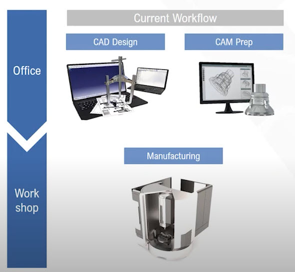
A workflow within a software program is the same as it is with anything in business: a serious of major steps or stages that a person goes through while developing a project from start to finish. In CAM software, the workflow is often referred to as the toolpath. The workflow involves calculating the actual paths that will drive where the tool will move on the machine.
Below you see a classical workflow used by many manufacturing companies the same way. A CAD part is imported in a CAM system or on the machine controller. After the CAM process the part will be manufactured on the machine.

An opportunity to improve upon this workflow with a more automated solution is machine-driven CAM programming, or self-driving CAM. With the self-driving CAM approach, the preparation for CAM is easy and can be performed even by inexperienced operators independent of the part complexity. Each of the necessary decisions for CAM programming processes are taken care of by the system automatically. In summary, self-driving CAM enables efficient manufacturing for customized parts, which can propose significant value and opportunities for job shops and machine tool builders.
Learn more about self-driving CAM in this webinar: Automated CAM Programming.
Realizing a Development Project in CAM Software
CAM allows application developers to be in the driver’s seat of the manufacturing industries digital transformation by enabling automation in their applications. When it’s boiled down, application developers want to build CAM applications that make it easy for a CAM engineer to collaborate with a CAD or CAE engineer during design iterations.
CAM application developers require best-in-class development components for their development project. With a CAM vendor or CNC machine builder, the solution will be their own software, not a generic CAM product from the market. They own it, they support it, they can develop it on their own, and they can enhance the software for their customer’s requirements. They will implement their expertise for their customers and optimize the software for their workflows or for specific machines. The 3D components behind the software will help CAM vendors enter the current CAD ecosystems of different industries.
Watch videos and read case studies related to the CAM industry


.jpg?width=450&name=Application%20Lifecycle%20Management%20(1).jpg)


