


Since its introduction in the 1980s, IGES (short for “Initial Graphics Exchange Specification) was the main computer aided design (CAD) format used for enabling the sharing of CAD files.
A result of the US Air Force’s (USAF) Integrated Computer Aided Manufacturing (ICAM) project from 1976-1984, IGES became a widely adopted vendor-neutral CAD format. Today, IGES files can be read by a wide range of the CAD industry’s leading solutions, including SolidWorks.
However, despite its extensive use, IGES’ value is becoming increasingly limited. First, its last official specification (Version 5.3) was released in 1996 - i.e. 22 years ago. Second, changes in the additive manufacturing space require CAD files in various stages in the design and analysis workflow to exhibit various details that are not supported by IGES.
Today, the growing use of advanced CAD formats - such as SolidWorks’ SLDPRT - in many engineering workflows means that CAD software suites must be able to read more than only vendor-neutral formats such as IGES.
Why IGES?
IGES’ strength lay in its vendor-neutrality. It was basically a common standard that could be - and ultimately was - adopted by most industry leading CAD suites, including SolidWorks, Solid Edge, Autodesk Inventor and others. It did not matter what CAD suite a specific engineering or design team had been using, they each could read and write IGES files.
In addition to widespread compatibility, IGES files could also contain core design elements, such as: 2D and 3D geometry (including lines, circles, planes, ellipses, spheres and others); bounded geometries; B-Rep; assemblies; colors; names; and layers.
Practically, engineering and design teams did not have to worry about whether their CAD file (if converted to IGES) could be read by the receiving party. In fact, not only would the file recipients be able to see your design’s geometry, but IGES’ limitations - e.g. its inability to retain meta-data from complex CAD file formats - also protected the original designer’s intellectual property (IP).
However, IGES’ limitations are more trouble than they’re worth, especially from the perspective of trying to complete engineering processes in a timely and cost-effective fashion. Today, a single manufactured system requires the design and testing input of multiple suppliers, which makes full-fidelity sharing between different workflows essential. Thus, a CAD viewing software must have the ability to readily view advanced CAD formats, such as SLDPRT.
What is a SLDPRT File & Why Use It?
Natively viewable and generated in SolidWorks, a SLDPRT (short for SoLiDworks PaRT) is a CAD file that contains a single 3D object or “part”. In turn, this one SLDPRT file or “part” can be combined with others of the same file type to construct an assembly file - i.e. SLDASM.
Since its initial release in 1995, SolidWorks captured 32% of the CAD market by 2016. In fact, in 2016 it was in use by well over 200,000 companies, three million customers in 80 countries and an output of two million SolidWorks-trained students graduating every year (SolidWorks).
The Computer Aided Design (CAD) Market in 2016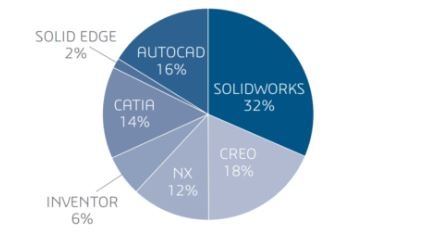
Source: SolidWorks
Simply put, SolidWorks is the most widely used CAD suite in the world. Thus, it makes no sense to ignore equipping your CAD suite from reading and writing SLDPRT and SLDASM files. Here are a few reasons why SolidWorks is gaining ground.
3D CAD
SolidWorks is a solid modeler capable of constructing 3D design parameters, design intent and features. As a 3D CAD suite, SolidWorks is praised for its ease-of-learning or relatively lower difficulty curve, enabling engineering teams with only prior non-SolidWorks experience to quickly embrace it.
Simulation & Visualization
Besides design, SLDPRT files can also be analysed through built-in simulation and visualization tools. Those using SolidWorks are able to test parts through static linear, dynamic analysis and sequential multi-physics simulations. SolidWorks’ visualization capability enables engineering teams to show full-fidelity design intent of their parts and complete systems.
Product Data Management
SolidWorks teams also leverage streamlined data file management and documentation features that make storing, retrieving and editing design data between different team members an easier process than on competing suites. In fact, in 2006 SolidWorks users reported strong increases in efficiency and output compared to their preceding CAD suites.

Source: SolidWorks
ECO: Engineering Change Orders
Though SolidWorks is the leading CAD suite in-use, 68% of the overall CAD market in 2016 was using competing CAD suites. It is unrealistic to expect every company to shift tested and deeply established workflows for new software. Likewise, other CAD suites may offer specific functions or features needed by certain teams or companies.
Thus, enabling these different teams and workflows to readily read SLDPRT is critical. In fact, with the extensive use of SolidWorks today, many companies will at least be seeking the ability to read SLDPRT files without having to pivot to SolidWorks.
Make Your Apps Read Files in SLDPRT Format with InterOp 3D
Those developing applications for properly reading SLDPRT in non-SolidWorks workflow design and testing environments must leverage the right tools. Naturally, Spatial’s 3D InterOp software development kit (SDK) for data translation should be first-of-mind.
Besides being a robust SDK in terms of retaining design intent (of a SLDPRT file running in a non-SolidWorks CAD suite) with high application performance, Spatial shares the same parent company as SolidWorks - i.e. Dassault Systèmes. In other words, applications using 3D InterOp will leverage Spatial’s ability to enable access to the latest developments.
In addition to SLDPRT, your applications will also be able to natively read CAD files in a large number of other formats, including (among others) Autodesk Inventor, CATIA and Solid Edge.
Thanks to 3D InterOp, interoperability between different engineering workflows need not be confined to IGES’ limitations. Rather, your applications now have the opportunity to provide a solution that enables a more seamless CAD file sharing process, one that pays dividends for end-users in terms of reduced technical difficulties, time-to-market and other inefficiencies.
Contact Spatial today for an opportunity to evaluate the 3D InterOp SDK.

.jpg?width=450&name=AdobeStock_487440650%20(1).jpg)


.jpg?width=450&name=Application%20Lifecycle%20Management%20(1).jpg)


