
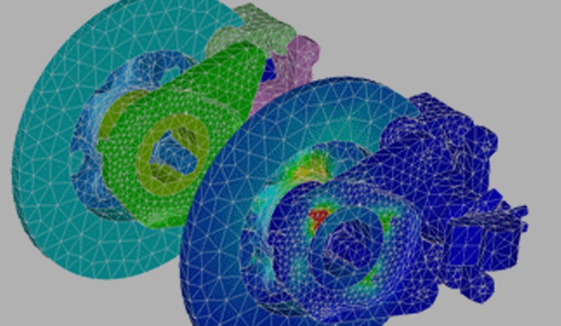

Analysis applications often use solid models generated by CAD systems as their input; for example, the structural analysis of an engineering model. The user of the system applies a set of loads and boundary conditions to the model, and then the software performs its analysis and supplies a set of deformations or stresses in the material, allowing an engineer to look at the results and decide whether the design fits its purpose.

The Issues with an Iterative Process
This process is great if the designer got it right first time, but often the design/analysis cycle is an iterative one where analysis reveals that a tweak to the design is required. The designer then makes the required modification, and the design/analysis loop starts again. Over several iterations the design tends towards the correct solution.
The problem with this iterative process is that setting up the loads and boundary conditions is time consuming for the structural engineer. The second issue is the possibility (or even probability) of introducing human error into the system due to the iterative, manual process. If there are a lot of iterations, then the potential cost savings of both reducing setup time and fixing errors is huge.
Identifiers over Geometry
The good news is that the CAD systems used in designing the models generally have a scheme for identifying the topology (faces and edges) of the model. Feature-based CAD systems define the model as a set of parametric shapes (and associated attributes), each one applied to the model in turn to build up the complex geometry that is an engineering part. The user is able to modify the parameters of a feature, and the system in turn, rebuilds all the affected geometry with the new value. For this rebuilding to work repeatedly, the system has to be able to keep track of which piece of geometry each feature is based on, usually by means of an identifier.
As a very simple example, imagine placing an engineering fillet on the end face of an extrusion; the associated feature definition could be “Apply a fillet of radius 5 mm to Face A”. This definition contains a feature parameter of 5 mm and an identifier, Face A. Now if the extrusion definition and the length are changed, then the geometry of Face A is changed; however, the fillet feature still works as long as the identifier (which is the new end face) has the same name.

Permanent Identifiers and One-Way Associativity
Going back to the analysis system, if the loads are applied in terms of the identifiers rather than directly to the geometry, then the reapplication of those constraints to a modified version of the model can be done automatically. As long as the changes in the model are small, the CAD system leaves the majority of the identifiers unchanged — as is usually the case for the design tweaks made in an iterative cycle. As a result, the software can automatically locate them in the next cycle.
The use of these permanent identifiers in a model used in an iterative cycle is called one-way associativity — there is an association that is kept in the direction of CAD model to analysis model. This principle can also be extended to a much wider range of application areas where this type of iterative approach takes place, such as measurement or multi-CAD architectures.
The Benefits of Using One-Way Associativity
Applications operating in an iterative design/analysis cycle can benefit from using one-way data associativity to automatically reapply the setup data during each cycle, providing savings in both the time to reapply data and a reduction in possibility that human errors could be introduced. Of course one of the pre-requisites for such a system is being able to extract the permanent identifier information, which is where a good 3D data translator comes in useful.
.png?width=450&name=AdobeStock_188705270%20(2).png)


.jpeg?width=450&name=AdobeStock_289023609%20(2).jpeg)


.jpg?width=450&name=Application%20Lifecycle%20Management%20(1).jpg)


