

Qt Tools for 3D Software Development Kits
When software developers opt for tools that are cross platform, they often turn to Qt. Qt is arguably the most popular toolkit for making applications that can run on Windows, Mac or Linux with little additional effort. Spatial’s 3D software development kits can be paired with Qt to produce enterprise quality applications that are platform agnostic.
To help developers get started in this environment, here we present a small collection of files that can be used with qmake for generating makefiles and IDE workspaces that are configured to use software components from Spatial. We’ve also included a simple project that illustrates the use of these add-ons.
Prerequisites
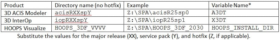
Qt 5.4 is the current version available, but these scripts should work with earlier and future versions as well. You’ll also need an installation of the Spatial software components for each platform you want to support. To take advantage of the qmake scripts provided here, install your Spatial components in a common root directory and name the product folders according to the following naming convention:
By using a network share as the installation location, all Spatial components for all supported platforms can be installed to the same location. The qmake system has support for prefix headers (sometimes called pre-compiled headers) which can be used dramatically decrease build times when third party software components such as ACIS are shared on a network drive.
* If you don’t install your components this way, you can specify their locations individually by setting the variables in your shell environment or in your qmake project file prior to using the pri files provided here.
Usage
In order to add support for Spatial components, edit your product’s .pro file and add the following variables:
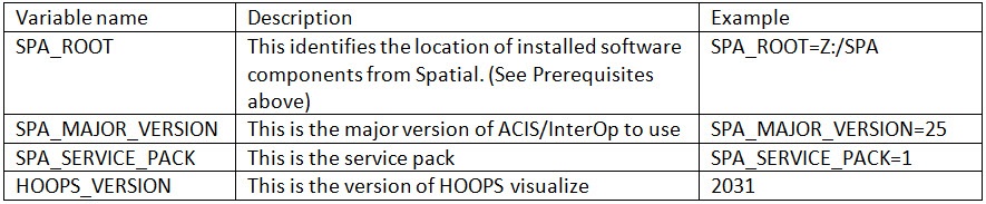
With this information, your environment is completely specified, and all that’s left to do is include the components you want to build into your application.
QT .Pri & .Pro Files
Here is an example of a .pro file that takes advantage of this build configuration:
# Specify default values for versions
SPA_MAJOR_VERSION=25
SPA_SERVICE_PACK=1
# Allow local configuration file to specify SPA_ROOT
# and to override default versions as needed.
# config-local.pri should not be kept in revision control
# but created and modified by the developer in their working copy
exists(config-local.pri):include(config-local.pri)
isEmpty(SPA_ROOT):error(Edit config-local.pri to set SPA_ROOT)
!include($$SPA_ROOT/spa_pri/acis.pri):error(Unable to include acis.pri)
!include($$SPA_ROOT/spa_pri/iop.pri):error(Unable to include iop.pri)
message(A3DT: $$A3DT)
message(X3DT: $$X3DT)
message(ARCH: $$ARCH)
TARGET=hello_world
CONFIG*=thread console
macx:CONFIG-=app_bundle
SOURCES += main.cpp
After including any of the .pri files provided, you can access the values they define. This can be useful for automatically writing a batch file that augments your PATH environment variable, which makes dynamic loading of the libraries much easier. For example:
win32 {
  bs_a3dt = $$replace(A3DT, '/', '\\')
  cmd = echo 'set PATH=$${bs_a3dt}\\$${ARCH}$${d}\\code\\bin;^%PATH^%' > acisPath.bat
  message($${cmd})
  system($${cmd})

  cmd = echo 'set A3DT=$${bs_a3dt}'>> acisPath.bat
  message($${cmd})
  system($${cmd})

  cmd = echo 'set ARCH=$${ARCH}'>> acisPath.bat
  message($${cmd})
  system($${cmd})
}
The variables A3DT and ARCH are defined by including acis.pri. The forward slash to backslash conversion is done because all paths in the qmake environment use forward slashes, while the windows command prompt expects backslashes.
In addition to modifying your PATH variable, the batch file created by the above snippet sets A3DT and ARCH shell environment variables. This can be useful when opening and building visual studio solutions that ship with Spatial’s software components.
Link to Zip File
Summary
By pairing Spatial’s software components with the power of Qt, you can create applications quickly and easily that run on all the major platforms. By using .pri and .pro files, configuring a build environment is easy, reliable, and flexible. Even if you choose not to use Qt as your GUI toolkit, you can use qmake as a platform independent build tool for easily generating makefiles and IDE workspaces.
.png?width=450&name=AdobeStock_188705270%20(2).png)


.jpeg?width=450&name=AdobeStock_289023609%20(2).jpeg)


.jpg?width=450&name=Application%20Lifecycle%20Management%20(1).jpg)


