Skip to content

Clashing Geometry in BIM Datasets

David Hornsby | 26-11-2018

To check clashes in a large BIM dataset, it is much faster to start by performing a simple no-clash check and then look in more detail at the cases that may have interactions. For working with large data sets, a scalable solution can be achieved by parallelizing the bounding box comparisons.

Clash-Detection-fig-1
Hexagon pattern 1

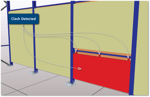
 A major benefit of constructing a building virtually is the cost savings gained by identifying errors in the design before they are found on site. One of the more common errors that can be avoided is when two objects overlap in space or clash. For example a beam that should stop at a wall may have been wrongly dimensioned so that when placed on site, it passes through the wall. Right through or only partly through, either way it is very costly to fix if it is only identified as the wall is being built.

The traditional approach to resolving these issues is with 2D drawings and tracing paper —a manual, slow and error-prone process. In complex situations the clash may well be missed and likely a more expensive situation to resolve on site too. Fortunately in modern BIM systems, the 3D representation of the building in software lends itself to automating clash with many CAD products or even with available clash analysis applications.


Considerations when Clashing 3D Models

When implementing geometric algorithms on a BIM dataset, it is worth remembering that there is likely to be a lot of data. A function that works between two blocks in an experiment may be very slow when repeated for a whole block of flats with 10s of thousands of structural elements.
 

Clash-Detection-fig-1

Figure: Clash Detection Identifies Overlapping Bodies
Clash-Detection-fig-2

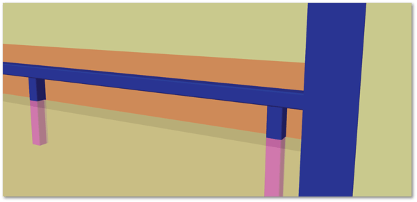
Figure: Boolean Intersection Calculates the Common Volume
Clash-Detection-fig-3

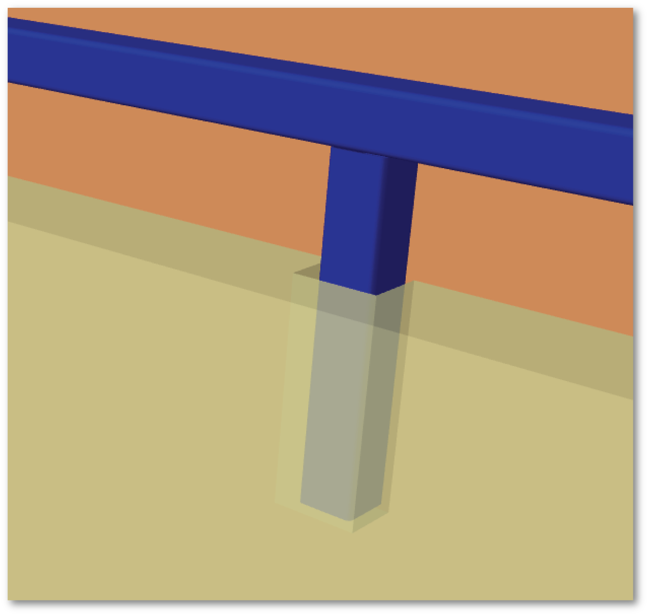
Figure: Void Introduced to Remove Clashing

Boolean Intersection

Boolean intersection in geometric terms will give you “a body that contains all points that are common to both of the two input bodies.” Maybe surprisingly, Boolean intersections can be a very expensive calculation, so while it is very useful if you know that you need to make a hole in a wall to place a window, it will be a slow mechanism to search for clashes in an entire building.

Geometric Clash Detection

At a geometrical level two bodies are clashing if there is a point on one body which is within a tolerance of the other body. Geometric clashing as faster than the Boolean as it will tell you about the interactions between two bodies without calculating the volume of intersection. A full clash detection will identify all the pieces of the bodies within the tolerance, though in many cases, it is enough just to detect that a clash occurs and stop at that point, simply returning a true/false answer.

Finding out how the bodies clash can be quite slow, but identifying that they don’t clash is very quick in most cases. The bounding box of a body is simply a cuboid that represents the minimum and maximum in each of the three ordinate directions. To check that the boxes do not clash, all that is needed is to check that each of these three ranges do not overlap, which is usually the first stage of a clashing algorithm.


Assembly Clash Detection

In general geometric modelers have limits in their dynamic range: the lower end is the smallest distance between two points before they are considered coincident, and the upper end is the largest model size that the modeler can handle. These limits are imposed by the accuracy of floating point arithmetic in computers. Most BIM projects will be made up of a very large number of components, where each component is of a size easily modeled; however, those components can easily be placed kilometers apart, especially in multi-site projects. To avoid geometric errors from large coordinate values, applications create geometry in the component’s object space and keep associated transforms in the assembly data to position the models in the site coordinates.

An additional optimization that is often used with such an assembly structure is to keep the bounding box of each component in the assembly data. The bounding box consists of the range of the model in X, Y and Z, so it is very quick to check for a no-clash condition between two bounding boxes, and then do some additional checks if the boxes overlap. Performing a large number of these no-clash comparisons with such simple data objects is easy to parallelize in software.

Conclusion

To check clashes in a large BIM dataset, it is much faster to start by performing a simple no-clash check and then look in more detail at the cases that may have interactions. For working with large data sets, a scalable solution can be achieved by parallelizing the bounding box comparisons.


Learn More:


You might also like...

5 Min read
3D Modeling
What is digital manufacturing? Here’s a simple digital manufacturing definition: the process of using computer systems...
5 Min read
CGM Modeler
Software components are like the stage crew at a big concert performance: the audience doesn’t see them, but their...
Application Lifecycle Management Flow
4 Min read
CGM Modeler
When you hear the term, Application Lifecycle Management (ALM), you likely think about the process that a software...
9 Min read
CGM Modeler
SLS in Additive Manufacturing is used to convert 3D CAD designs into physical parts, in a matter of hours.
8 Min read
CGM Modeler
There’s a lot of confusion around what the terms additive manufacturing and 3D printing mean.
4 Min read
3D Modeling
Additive manufacturing, often referred to as 3D printing, is a computer-controlled process for creating 3D objects.
5 Min read
CGM Modeler
Computational Fluid Dynamics (CFD) is a type of analysis that provides insight into solving complex problems, and...
2 Min read
CGM Modeler
WRL files are an extension of the Virtual Reality Modeling Language (VRML) format . VRML file types enable browser...
Voxel model example
3 Min read
CGM Modeler
Voxels are to 3D what pixels are to 2D. Firstly -- let’s examine what pixels actually are. Everything you see on your...
Point_cloud_torus
2 Min read
CGM Modeler
Point-cloud modeling is typically used in the process of 3D scanning objects. Rather than defining surfaces through...
Polygonal Modeling
2 Min read
CGM Modeler
Polygonal (or polyhedral) modeling is the most common type of modeling for video games and animation studios. This type...
aerodynamics-CFD
9 Min read
CGM Modeler
Computational fluid dynamics (CFD) is a science that uses data structures to solve issues of fluid flow -- like...
BREP Model example
2 Min read
CGM Modeler
BRep modeling, or Boundary Representation modeling, is, in CAD applications, the most common type of modeling. BRep is...
Feature Recognition Zoomed
5 Min read
CGM Modeler
IN THIS ARTICLE: What is FEA (Finite Element Analysis) Principles of Finite Element Analysis and Simulation Software A...
3YourMind and Spatial
3 Min read
3D Modeling
As manufacturers begin to rely more and more on additive manufacturing (AM), moving from a few select piece parts that...
Voxeldance and Spatial
2 Min read
3D InterOp
To the uninitiated, 3D printing may seem a simple process — download your CAD file and hit print. But the world of...
BIM_word_cloud_web
2 Min read
3D Modeling
The construction industry has long taken advantage of prebuilt components, from prehung doors to prefabbed roof...
Clash-Detection-fig-1
4 Min read
3D Modeling
A major benefit of constructing a building virtually is the cost savings gained by identifying errors in the design...