The 2017 1.1 release of Spatial’s CGM™ Core Modeler improves the robustness of its feature recognition capabilities by extending the range of recognizable structures. Feature recognition rapidly identifies manufacturable structures in a model (such as holes, pads, logos, etc.), enabling users to group and perform subsequent operations on these constructs. This capability enables improvements to many workflows, such as reducing complexity for downstream simulation and analysis.
For the uninitiated, CGM Core Modeler provides a powerful platform for 3D modeling and more. The CGM Core Modeler supplies functions to create, modify, and query objects, as well as support visualization, simulation, and analysis. As the 3D modeling kernel used in Dassault Systèmes’ V5 and 3DEXPERIENCE Platforms, CGM Core Modeler has been the foundation of V5 products for more than a decade, proven in the most challenging application environments and used by some of the world’s largest manufacturers.
Recognizing Model Features
When a model is loaded into CGM Core Modeler, routines are run, to automatically recognize a range of features. Previously, CGM Core Modeler could recognize constant-radius fillets in an imported model, relying on user intervention to identify other key features. With this release, CGM Core Modeler can recognize holes, pads, pockets, slots, notches, and logos, providing parameter information back to the host application. CAM applications can also use these feature parameters for building manufacturing plans or optimally deciding the order of features to be machined.
Holes
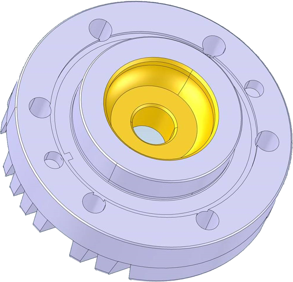
The latest version of CGM can now correctly identify a range of hole types. In addition to the standard CAD-type holes. such as simple, countersunk, counterbored, and counterdrilled holes, CGM can also recognize general holes.

Figure: Standard Holes

Figure: General Holes
Pads and Pockets
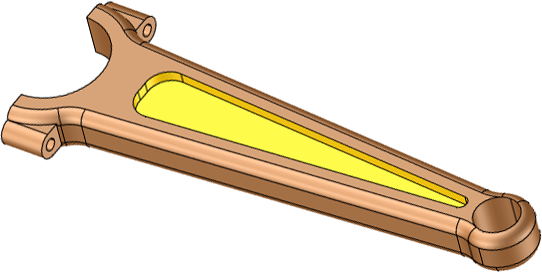
Pads (raised areas) and pockets (including through pockets) can now be recognized in single extrusions with a general (closed-loop) cross-section.

Figure: Pocket Recognition
Slots and Notches
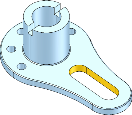
As if pad and pocket recognition were not enough, CGM can also recognize slots that have rounded or rectangular end walls. Moreover, fillet and chamfer decorations are allowed on the supports and ends. Notches with rounded end-walls are also recognized.

Figure: Slot Recognition
Logos
CGM can now identify sharp logos (G1 discontinuous), assuming that these logos are:
- Sufficiently small
- Boundary edges have a consistent convexity

Figure: Logo Recognition
Fillets
The enhancements in the release extend to fillet recognition. Added is recognition of variable radius fillets, as well as the junctions between both constant and variable radius fillets.
Improved Workflows
Automatic feature recognition greatly facilitates two workflows:
- Analysis and simulation (FEA, CFD)
- Cataloging and searching
Rather than spend many man-hours to manually identify and classify structures, users can concentrate on downstream analysis. With robust feature recognition, more features can be identified, improving the ease of use, accuracy and efficiency of these workflows.
Once identified, features can also be grouped for easy editing, searching, and cataloging, for example, when completing a cost analysis and manufacturing plan. Additionally, the manufacturing plan between similar parts can be aligned to reduce costs, whether it is reducing the number of screw types or the range of subassemblies purchased from an outside vendor.
For analysis and simulation, feature recognition is used to identify certain structures for removal to simplify downstream analysis; for example:
- Modeling the airflow over a car where gaps, windshield wipers and other protrusions can cause noise in the analysis, making it harder to optimize the fundamental design and increasing the computation time and resource need.
- Performing finite element analysis when, for example, measuring the strength of an airframe, where removing items that do not materially affect the results such as the interior finish, non-structural bolts, etc., can greatly improve compute time.
With 2017 1.1 Release of CGM Core Modeler, a wide range of feature recognition capabilities have been added, allowing OEMs to add new features to their end products. And OEMs can look forward to additional recognition capabilities in the future.


.jpg?width=450&name=Application%20Lifecycle%20Management%20(1).jpg)


