2022 1.0 Enables Data Prep for Digital Dentistry & Sheet Metal Manufacturing, Improves PMI Exchange, Simplifies ACIS Multi-Threading, and more
Release Highlights:
- Modeling and Data Preparation for Digital Dentistry: CGM Polyhedra Enables Easy Undercut Filling and Tooth Cap Generation
- Unbending of Sheet-Metal Parts with Even More Speed: Automatic Unbending
- Obtain Finite-Element Results Faster: Creation of Mid-Surface Sheet-Bodies with the 3D ACIS Modeler
- Easy-to-Implement Parallelization in the 3D ACIS Modeler: Quickly Multi-Thread Your ACIS Workflows
- From Smaller to Larger with 3D InterOp: Import of Large-Scale Models into CGM-Based Applications
- Enable Industry 4.0 with 3D InterOp: Import of Tolerance Modifiers
- 3D Precise Mesh Extends CFD Workflows: Automatic and Robust Boundary-Layers
- Other Highlights in 2022 1.0
Modeling and Data Preparation for Digital Dentistry: CGM Polyhedra Enables Easy Undercut Filling and Tooth Cap Generation
Tessellated models composed of meshes are ubiquitous in modern workflows across various industries, like the dental industry. Unlike precise solid-geometry normally seen in traditional engineering design and manufacturing applications, mesh-geometry is ideal for the organic anatomical shapes encountered in dentistry and other medical applications that model human anatomy.
However, tessellated models – often in the STL file format – are notoriously prone to quality problems in so-called “dirty” models. For example, connectivity in meshes between constitute triangles may be corrupted, resulting in non-watertight meshes, triangle normals may be incorrect, triangles may overlap, or gaps between triangles may be present. Therefore, the need to heal tessellated models and correct meshes is paramount.
Moreover, after healing, there is often a need to edit and modify mesh geometry just like traditional solid geometry. For example, one may want to scale a mesh, extract the mesh boundaries, or join two meshes depending on the specific workflow.
CGM Polyhedra has robust tools to both heal and modify mesh-geometry, including new functionality to fill gaps between meshes and create/modify meshes by sweeping polylines with draft-angles. These new capabilities in CGM Polyhedra are best illustrated by three workflows from dentistry as listed below.
- Fill open regions in the form of irregular holes that may be a result of poor upstream scanning in tessellated models of jaws.
- Fill concave undercut regions between the tooth and the jaw with poly extrude and sweeps.
- Smoothly join the tessellated model of a crown (tooth-cap) with the tessellated model of a root (tooth-root) by filling the region between the boundaries of the two meshes.
1. Fill Non-Planar Holes in Meshes: Holes in Mesh of Maxillary (Upper) Jaw
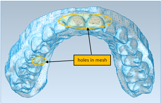 |
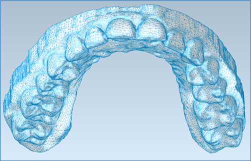
| Tessellated model of a maxillary (upper) jaw with non-planar holes in mesh with missing triangles |
intraoral scanner. The scanner optically captures positional data to render a 3D digital impression of the patient’s teeth. Ultimately the impression is converted to a tesselated model and typically saved in an STL format.
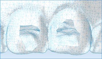 |
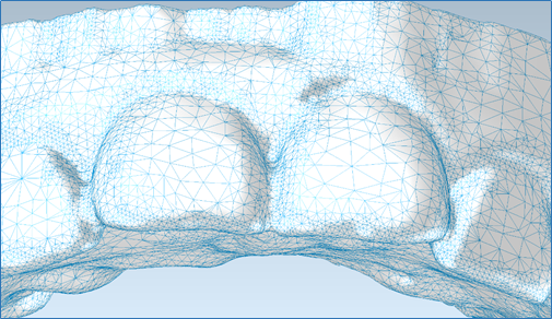
| Zoom of holes in front incisor teeth |
 |
|
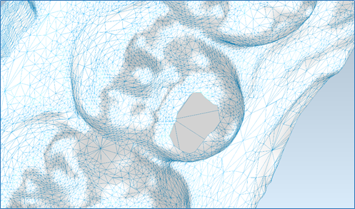
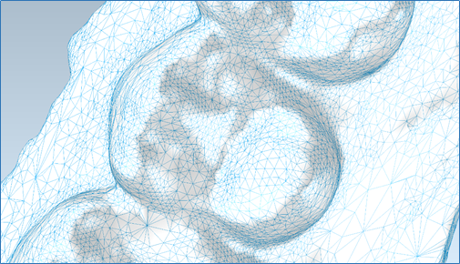
Zoom of the hole in the first molar tooth |
 |
|
All holes smoothly filled by CGM Polyhedra; mesh is now watertight |
filling process.
The resulting watertight mesh of the jaw clearly shows that all holes have been filled. Further smoothing can be applied if desired. Now the jaw is ready for additional downstream dental workflows described next.
 |
 |
|
Zoom of holes in front incisor teeth: holes filled |
Zoom of the hole in the first molar tooth: hole filled |
2. Fill Concave Undercut Regions: Join Tooth to Jaw with Poly extrude and Sweep
 |
|
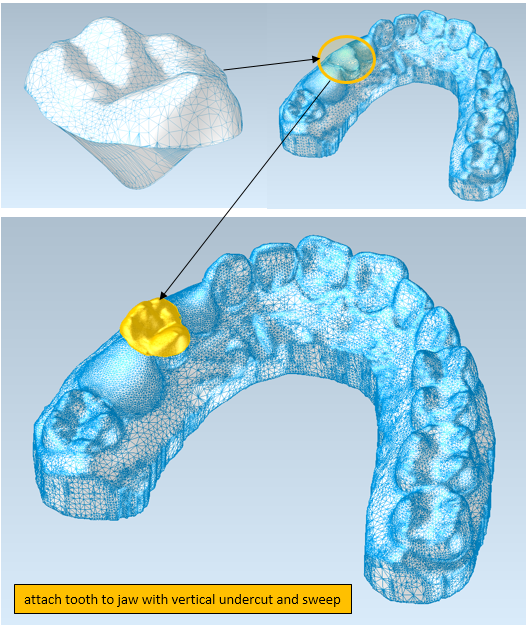
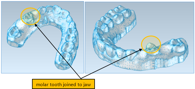
Tooth and Jaw with concave undercut regions |
There are multiple scenarios in dental modeling where undercut regions between the tooth and the jaw need to be filled. Leaving the concave undercut space as is and then designing tooth guides for such tooth-jaw configurations will result in guide fit issues. Such filling can be accomplished with polyline extrusion, and for a fill with a draft, the poly sweep can be leveraged.
Before extruding or sweeping, each mesh is healed using the same process as for filling holes.
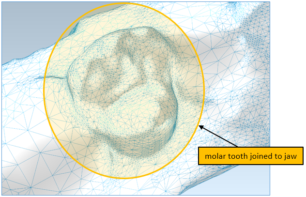
Now the undercut regions between the two meshes – the molar tooth and the jaw – can be filled. First, the outer boundary or silhouette of the molar tooth is extracted from the mesh and projected over the jaw. Then through a set of Boolean operations, an undercut region – also a mesh – is created between the bottom of the molar tooth and the jaw.
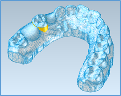
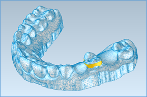
Undercut region between molar tooth and jaw
In some scenarios, there may be a requirement to have a draft angle to the undercut. This can be accomplished by sweeping the boundary of the undercut with a draft angle. In this case, the top boundary of the undercut region is extracted and then projected just below it. Then a swept region with a shallow draft-angle is created with new functionality in CGM Polyhedra around the perimeter of the projected boundary. This swept region is also a mesh and provides a smoother, more organic transition between the undercut region and the jaw.
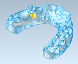
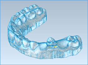
The swept region between undercut region and jaw
3. Smoothly Join Two Meshes: Crown to Root by Filling the Region Between the Two Boundaries
The last workflow smoothly joins the boundary of a crown (tooth-cap) with the boundary of a root (tooth-root). This is called capping because the crown caps the root.
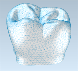
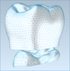
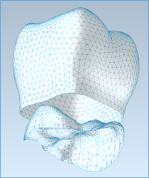
Crown and root meshes
Second, CGM Polyhedra smoothly joins the two boundaries and hence the two meshes. As a result, the crown is now smoothly affixed to the root.
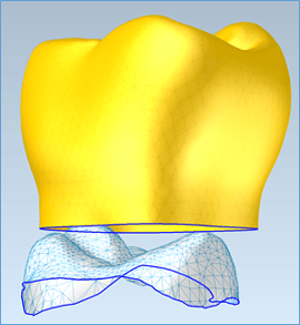
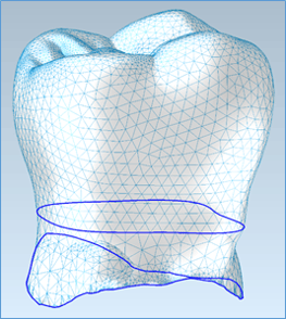
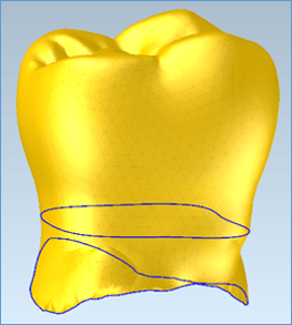
Overall, the three digital dental workflows – hole-filing, undercut-filling, and capping – are simplified with new functionality in CGM Polyhedra. Further, the new healing and modeling functionalities in CGM Polyhedra are applicable for industries beyond Dental. Consult Spatial today for more details on the myriad of ways CGM Polyhedra can enable similar workflows in your dental application.
Click to learn more about CGM Polyhedra.
Unbending of Sheet-Metal Parts with Even More Speed: Automatic Unbending
Often sheet-metal is the obvious choice for a myriad of industrial uses ranging from brackets and enclosures to ducting and car bodies.
An important step in the process of fabricating sheet-metal parts is the ability to virtually reverse the manufacturing process to unbend digital sheet-metal parts and lay the original sheet-metal design flat. New functionality in CGM Modeler now enables fast, automatic unbending of such sheet-metal parts.
 |
|
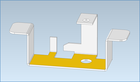
Typical sheet-metal part: select any flat-planar face |
Consider the typical sheet-metal part shown in the following figures (Sheet-metal part courtesy OSH Cut LLC). This sheet-metal part can be automatically unfolded in two easy steps. First, a flat-planar face is selected, as shown in the first figure. Any flat-planar face can be selected.
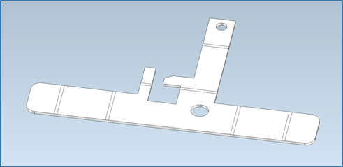 |
| Typical sheet-metal part: automatically detect and unfold bends all in one step |
Second, the selected flat-planar face is input into the new automatic unbend operator in CGM, which automatically traverses the part, detects all bends, and unfolds each bend. The process is extremely fast – indeed, the process is difficult to show in a video because it is so fast.
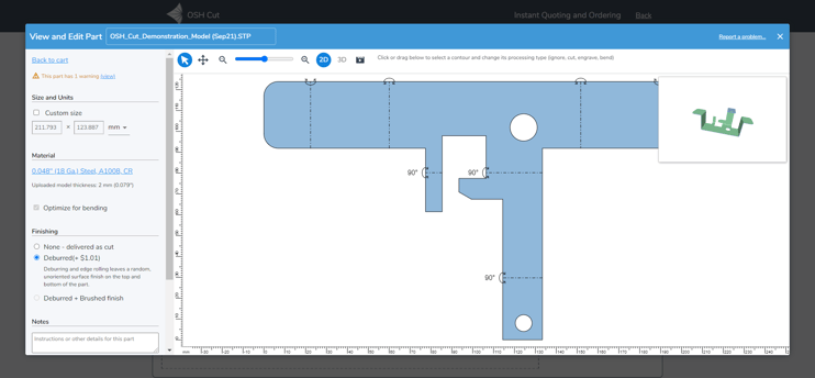
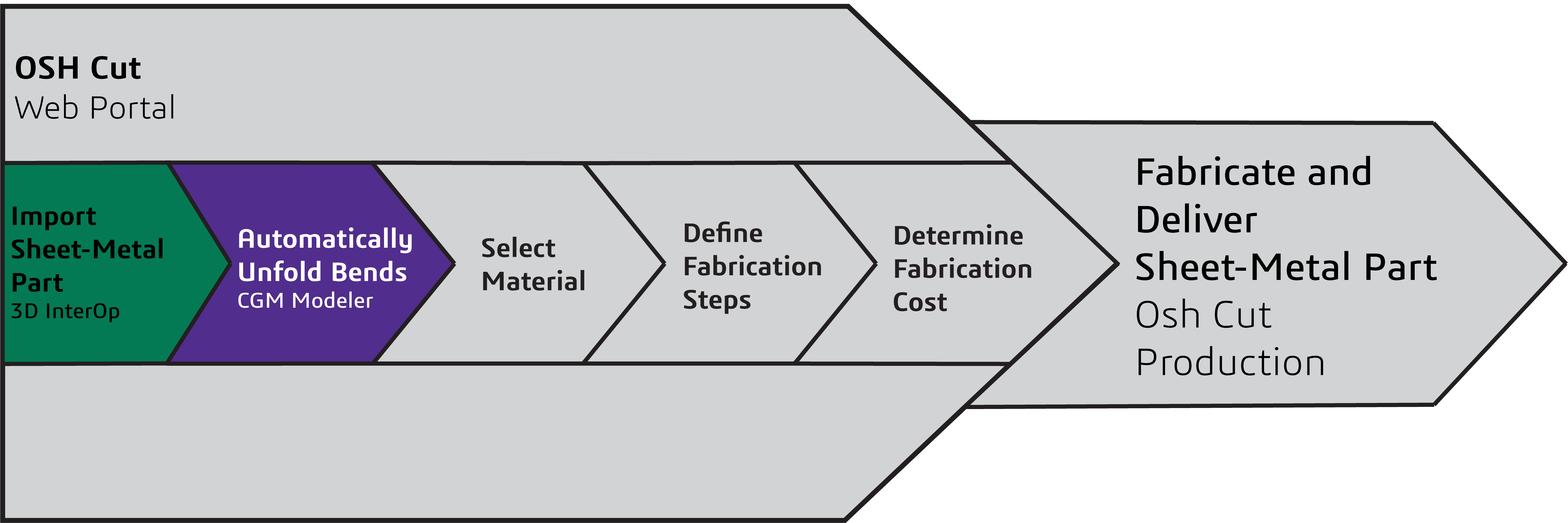
The entire virtual workflow for the import of sheet-metal parts and unbending of such parts can be implemented into any CAD-CAM software application with Spatial’s powerful CGM Modeler. For example, the following diagram illustrates the workflow in the context of a Spatial-enabled web portal for cost-estimation and fabrication of sheet-metal parts from OSH Cut.
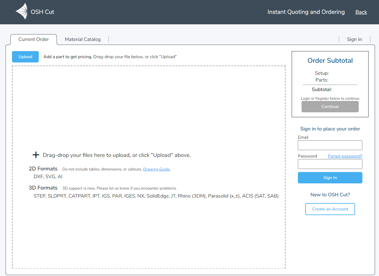 |
| OSH Cut web portal: user-interface |
Then a thickness and material are selected – in this case, 0.12mm (0.048in, 18 gauge) cold-rolled steel. The price for the fabrication of this sheet metal part is US$10.29. The customer can then elect to order the part, which will then be delivered to the customer’s doorstep in a few days.
Consult Spatial today for more details on the myriad of ways CGM Modeler can automate your digital manufacturing workflows.
Click to learn more about CGM Modeler.
Obtain Finite-Element Results Faster:
Creation of Mid-Surface Sheet-Bodies with the 3D ACIS Modeler
In its latest release, the 3D ACIS Modeler introduces the capability to extract sheet-bodies at the mid-surface between faces of solid bodies with the new function api_make_mid_sheet_body.
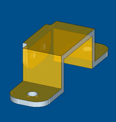
An example with api_make_mid_sheet_body illustrates an input solid-body, a sheet-metal part with wall thicknesses, and output, a new sheet-body at the mid-surfaces between opposite faces of the original solid-body.
 |
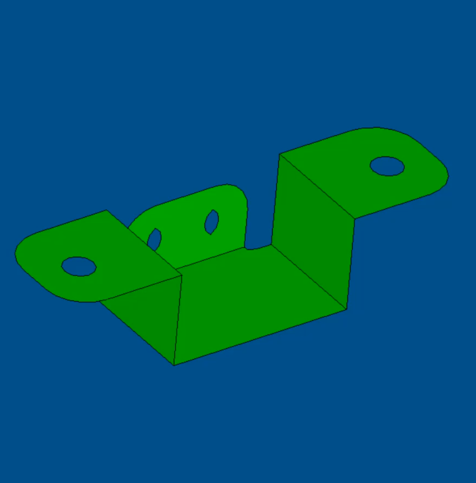 |
Creation of Mid-Sheet Sheet-Bodies: Input Sheet-Metal Solid-Body
But why would there be a need to create a mid-surface sheet-body from opposite faces in a thin-walled solid-body?
A good example is a finite-element (FE) workflow in a computer-aided engineering (CAE) application. For some models with part geometries comprised of thin walls, shell-elements instead of solid-elements suffice for an FE-simulation – both in terms of solution accuracy and certainly in terms of numbers of elements and hence solution efficiency.
Therefore, the ability of the 3D ACIS modeler to now easily and quickly extract the mid-surface between opposite faces of thin-walled geometries greatly simplifies FE-workflows. Instead of a series of manual modeling operations to extract the mid-surface for each pair of opposite faces in a complex thin-walled part, the user of a CAE application can simply click a button in the user interface that activates an ACIS-enabled workflow to extract the mid-surfaces. The mid-surfaces can then be meshed with shell-elements, and, say, for a structural analysis, loads and boundary conditions can be applied and a solution quickly calculated.
A specific example of the simplicity of an ACIS-enabled FE-workflow is the same solid-body sheet-metal part. A sheet-body at the mid-surfaces between opposite faces was extracted with one function called api_make_mid_sheet_body. The resulting sheet-body can then be easily meshed with structural shell-elements, using Spatial’s 3D Precise Mesh, resulting in a mesh to which appropriate boundary conditions and loads can be applied and a solution ultimately obtained. All without time-intensive manual modeling operations to extract the mid-surfaces – an aggravating model-preparation task that no CAE-engineer enjoys.
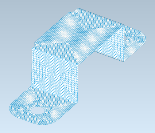
Finite-Element Mesh of Sheet-Body with Mid-Surfaces of Original Solid-Body
Consult Spatial directly for more details about how the 3D ACIS Modeler can simplify downstream workflows such as FE by extracting mid-surfaces from thin-walled solid bodies.
Click to learn more about the 3D ACIS Modeler.
Easy-to-Implement Parallelization in the 3D ACIS
Modeler: Quickly Multi-Thread Your ACIS Workflows
Tools for the parallelization of ACIS-dependent workflows via multi-threading have been present in the 3D ACIS Modeler for many years in the form of ACIS Thread Management. However, the tools in ACIS Thread Management have traditionally not been easily implemented by application developers – even for seemingly straightforward workflows.
Fortunately, this has now changed. In the latest release of the 3D ACIS Modeler, a new “helper” function, api_process_mt, is available, which greatly simplifies the implementation of multi-threaded, largely independent workflows involving ACIS data and functions. In fact, the same helper function was used by Spatial to implement a new multi-body clash function, api_n_body_clash, in the 3D ACIS Modeler.
A. New Helper Function: api_process_mt
A typical C++ code pattern for an ACIS-dependent workflow is a for-loop that repetitively invokes ACIS functions to perform a task with ACIS data, such as querying the faces of a body and doing something with the faces. While parallelization of patterns seems straightforward in theory, up until now, it has been quite difficult to implement in ACIS-enabled applications because of the relationships between geometric and topological entities in solid models and the need to track modeling steps in history streams.
Spatial now has a much more efficient and effective solution for very common tasks that lend themselves to multi-threading. In the latest release of the 3D ACIS Modeler, Spatial offers the new helper function api_process_mt to parallelize ACIS-dependent workflows via multi-threading. The interface for api_process_mt, including its data members for the history stream and status, and virtual methods for processing and copying, is all contained in a header-file called process_mt.hxx, which is now included in the ACIS package.
For many common ACIS-based workflows, the implementation of multi-threading for ACIS-dependent tasks is now easy, intuitive, and quick from a programming standpoint. Moreover, the performance gains from multi-threading can be drastic.
For example, consider an ACIS-dependent workflow that entails the subtraction of a half-space in a model with a large number of bodies. Subtraction for a single body requires about ten lines of code without multi-threading. But what about subtraction for any number of bodies in a multi-threaded manner? With the new helper function api_process_mt, only ten additional lines of code are needed for any number of bodies and multi-threading.
Furthermore, multi-threading allows much faster performance. Consider the same halfspace-subtraction workflow for a realistic model with 29000 bodies. The results clearly demonstrate drastically lower computation times with multi-threading enabled by api_process_mt.
|
ACIS-Dependent Workflow: Subtraction of Half-space
A model with 29000 Bodies
|
|
|
Thread Number
|
Computation Time [s]
|
|
1
|
13.94
|
|
8
|
2.47
|
|
16
|
1.32
|
|
24
|
0.97
|
B. New Multi-Threaded Multi-Body Clash Function: api_n_body_clash
The helper function, api_process_mt, can be used to parallelize ACIS-dependent workflows via multi-threading. In fact, the 3D ACIS Modeler team leveraged it to accelerate the development of api_n_body_clash, an API that detects clashes among multiple bodies.
With multi-threading, api_n_body_clash is significantly more performant than the naïve api_n_body_clash. Moreover, api_n_body_clash is more versatile than api_n_body_clash in that it detects clashes among more than just two bodies.
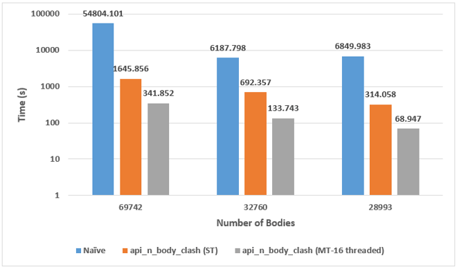
Clash detection performance: new function api_n_body_clash versus naïve function api_body_clash
The new helper function api_process_mt in the 3D ACIS Modeler can be used to quickly parallelize many common ACIS-dependent workflows without resorting to the ACIS Thread Manager. Moreover, Spatial used the same helper function to implement its new multi-threaded multi-body clash-detection function api_n_body_clash with clear performance and versatility improvements over the naïve function for clash-detection api_n_body_clash. Consult Spatial today for more details on how you can parallelize your ACIS-dependent workflows.
Click to learn more about the 3D ACIS Modeler.
From Smaller to Larger with 3D InterOp:
Import of Large-Scale Models into CGM-Based Applications
Large-scale models are typically associated with BIM-centric applications, which consume data for landscapes/terrains and buildings, whose dimensions range far outside dimensions for traditional CAD applications. For example, the building model, including internal structures and mechanical/electrical equipment, might range from millimeters to hundreds of meters. However, the building might be located in a larger landscape model that ranges to several kilometers. As a result, the ability to import models with wide dimensional ranges up to 100km is essential in providing flexibility to AEC workflows.
New for 2022 1.0, 3D InterOp allows the import of large-scale models with dimensions ranging from 1-100km into CGM-enabled applications. Such capability extends the capability of CGM from traditional mechanical-design workflows to architectural, engineering, and construction (AEC) workflows in the field of building-information management (BIM).
Furthermore, 3D InterOp offers the import of small-scale models with dimensions down to 10µm into CGM-enabled applications. This additional capability for small-scale models extends CGM into the semiconductor, electronics, and precision electro-mechanical industries, such as watches.
Consider a digital AEC workflow for designing an office building, which is situated on a large property encompassing many hectares. In this workflow, a digital model of the terrain of the property is first imported in a CGM-enabled BIM application. The terrain model for the property spans kilometers. However, 3D InterOp easily and efficiently imports the model.
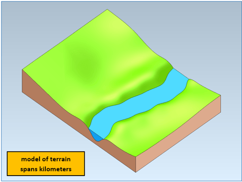
CGM-enabled BIM-application: import of terrain spanning kilometers by 3D InterOp
Second, the shell model of an office building is imported into the CGM-enabled BIM application. The building’s overall dimensions are much smaller than the terrain model; however, this is no problem with the enhanced scale flexibility embedded in 3D InterOp. Now the building is embedded in the terrain and building site and can be prepared for digital excavation with the aid of CGM Modeler. Such flexibility when importing models with different dimensional ranges is key to the AEC workflow in this CGM-enabled BIM application.
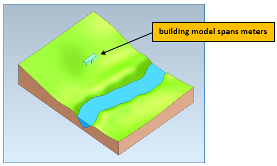
CGM-enabled BIM-application: import of building spanning meters by 3D InterOp
Third, the building site is prepared for the construction of the building with CGM Modeler. A driveway is constructed to the building site; then, the ground is excavated for the building’s foundation.
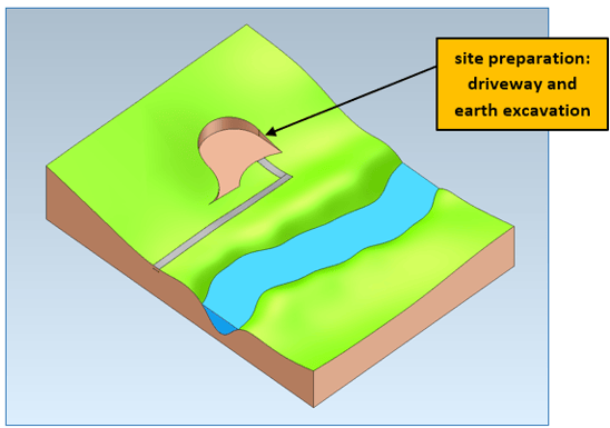
CGM-enabled BIM-application: site preparation for construction of the building
Fourth, the building’s foundation is created by digitally removing earth and filling it with concrete utilizing CGM Modeler.
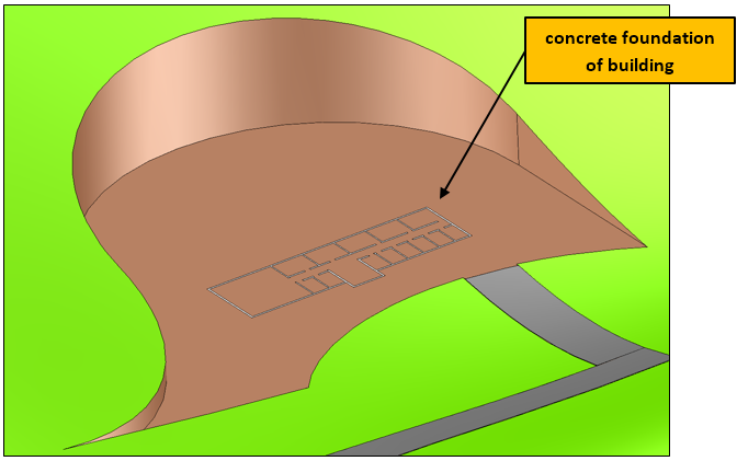
CGM-enabled BIM-application: create the foundation of building
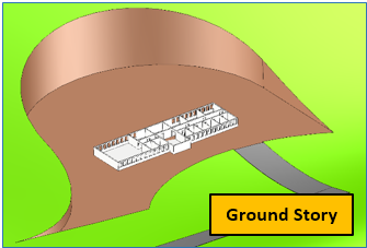
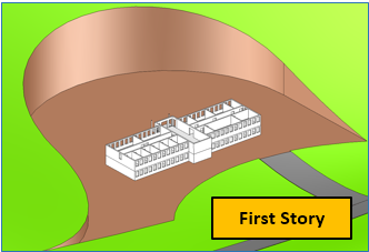
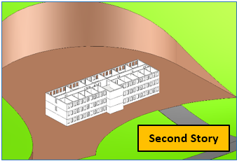
Fifth, the building is sequentially constructed story-by-story with CGM Modeler.
 |
 |
 |
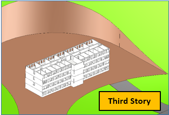 |
CGM-enabled BIM-application: building construction story-by-story
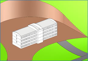
The building’s structure is now complete with a roof, columns, walls, windows, and doors. Later mechanical and electrical fixtures for each room and story can be added. The resulting model contains features ranging in dimensions from several mm to a few meters for fixtures in rooms to many kilometers for the terrain – all enabled with large-scale functionality in 3D InterOp for CGM-enabled BIM applications.
 |
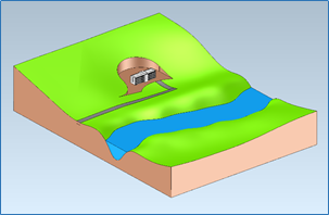 |
CGM-enabled BIM application: completed structure of building with terrain with different dimensions ranging from meters to kilometers
Consult Spatial today for more details on how 3D InterOp and CGM Modeler enable AEC-workflows with dimensional ranges from a few millimeters to kilometers – all easily and efficiently in one model. Click to learn more about 3D InterOp.
Enable Industry 4.0 with 3D InterOp: Import of Tolerance Modifiers
In addition to tolerance modifiers for material conditions, free states, and tangent planes, 3D InterOp from Spatial now supports the import of CZ (common-zone) and UZ (unequal-zone) modifiers embedded in digital CAD-models – including both graphical (human-viewable) and semantic (machine-readable) data. Furthermore, 3D InterOp now allows the import of more than two modifiers per feature control frame.
3D InterOp’s ability to import a range of geometric and dimensional tolerancing (GD&T) modifiers optimizes manufacturing (and measurement) processes with tolerance data that simultaneously controls the size, form, orientation, and location in one notation for both graphical and semantic workflows.
For example, the CZ modifier allows the application of the same tolerance and ultimately manufacturing process to different surfaces of a part. Similarly, the UZ modifier provides manufacturing options by providing a non-uniform way to apply tolerances resulting in an almost unlimited variety of shapes and conditions. Overall, the import and downstream use of tolerance-modifiers in digital applications supports both design and manufacturing flexibility and ultimately reduces fabrication costs.
Demonstration: Import of CZ Modifer by 3D InterOp
The tolerance modifier CZ indicates common-zones for which a given tolerance applies. A typical example of a tolerance with a CZ modifier is several surfaces with the same flatness tolerance.
Imagine the fixture model for part testing at an automotive supplier originally created in CATIA V5. The fixture has a 0.1mm flatness tolerance for two surfaces. In this case, 3D InterOp accurately imports and displays both graphical and semantic tolerance data for multiple surfaces with the CZ modifier.
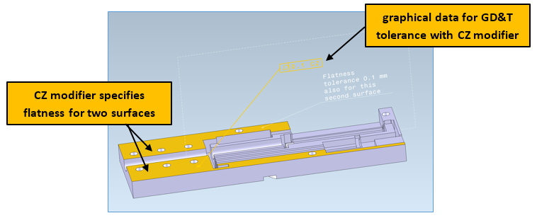
CZ modifier applied to GD&T tolerance for two surfaces after the import by 3D InterOp: graphical GD&T data
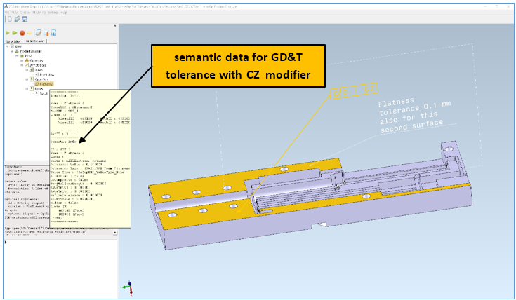
CZ modifier applied to GD&T tolerance for two surfaces after the import by 3D InterOp: semantic GD&T data
Demonstration: Import of UZ Modifer by 3D InterOp
The tolerance modifier UZ specifies unequal-zones for which an unequally disposed tolerance applies. UZ modifiers are a little trickier to understand than CZ modifiers; hence, a visual explanation is useful.
An example of a tolerance with a UZ modifier is the surface of a landing-gear strut from a small airplane in CATIA V5. The surface of the strut is complex – almost an ellipsoid but not quite – and has a tolerance of 0.1 units (e.g., mm). However, the tolerance also has a UZ modifier with a value of negative 0.1mm. Therefore, the surface of the strut can vary 0.02 mm outward and 0.08 mm inward from its theoretical profile. In this case, 3D InterOp accurately imports and displays both graphical and semantic tolerance data with the UZ modifier.
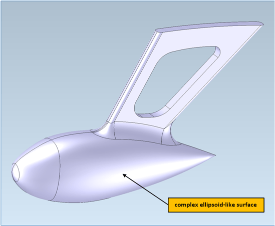
Landing-gear strut with complex ellipsoid-like surface
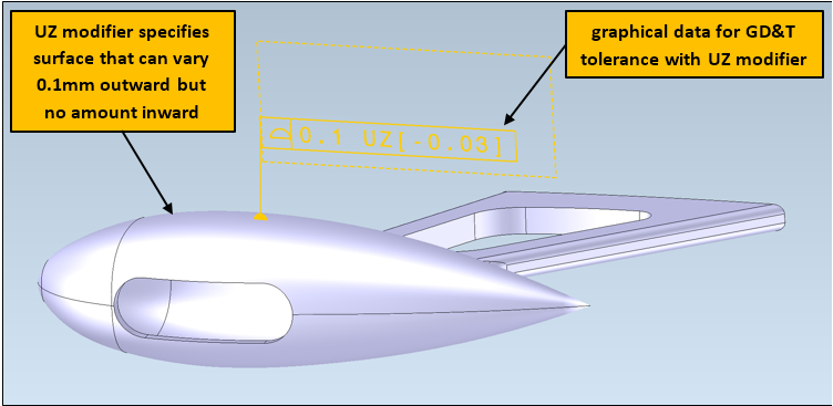
UZ modifier applied to GD&T tolerance for the surface after import by 3D InterOp: graphical GD&T data
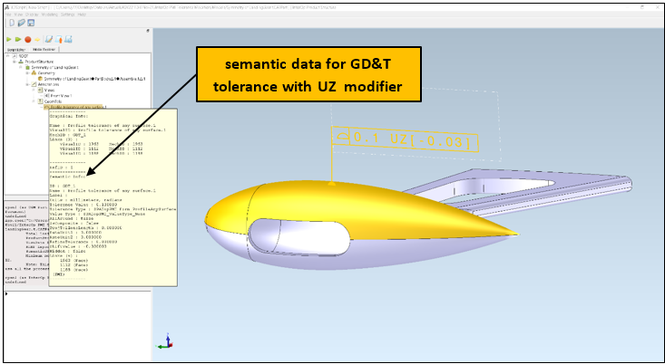
UZ modifier applied to GD&T tolerance for surface after import by 3D InterOp: semantic GD&T data
Please consult Spatial directly for more details about how 3D InterOp can enable more design and manufacturing flexibility with PMI data, such as GD&T tolerance modifiers in your digital workflow.
Click to learn more about 3D InterOp.
3D Precise Mesh Extends CFD Workflows:
Automatic and Robust Boundary-Layers
The generation of meshes continues to be a time-consuming task in workflows for computational fluid dynamics (CFD). Hybrid CFD in Spatial’s 3D Precise Mesh streamlines meshing tasks with a one-step, automatic, and robust CFD Hybrid mesh generation technology, including the management of boundary-layer mesh-generation, all controlled by user-defined parameters and functions.
New in 2022 1.0, 3D Precise Mesh now offers new functionality for Hybrid CFD in its quest to streamline the meshing of models for CFD analyses. In particular, Hybrid CFD now supports the mix of prismatic and hexahedral*** elements in boundary layers, automatically referencing input surfaces from CAD geometry and managing collisions, imprinting, smooth-blending, and adaptation features according to user-defined requirements.
Additionally, in this new release, 3D Precise Mesh keeps enhancing its capabilities for seamless meshing workflows, either for CFD and any other CAE workflows, by enhancing the management of discrete inputs of CAD geometry to generate quad-dominant surface meshes as well as second-order surface and volume meshes.
Click to learn more about the 3D Precise Mesh.
*** - Hexahedral elements in Boundary layers will be available in MeshGems V2.14, to be released by mid-November 2021.
Other Highlights in 2022 1.0
3D InterOp:
- Updated CAD version support
- Creo 8
- Parasolid 34
- NX 1980 series
- SOLIDWORKS 2022
- CATIA V5-6 2022
Refer to the 3D InterOp Release Notes for a complete list of updates
CGM Modeler/CGM Polyhedra:
- Mesh healing now allows decimation before healing to increase performance
- Cloning BRep bodies has been enhanced to support full object tracking capabilities.
- Added poly-based sample scripts to CGM documentation for relatively complex hybrid operators, like CATICGMHybDisconnect (3DScript command - CGM.disconnect). Refer to this table for more details on hybrid operators available in CGM.
Refer to the CGM Modeler release notes for a complete list of updates
3D ACIS Modeler:
- New API aids the unfolding/flattening of sheet-bodies
- New API facilitates the removal of free edges of sheet-bodies
- New option to scale swept profiles along paths
Refer to the 3D ACIS Modeler release notes for a complete list of updates

