
"2024 1.0 Delivers Advanced Functionality For Manufacturing Automation, Mesh I/O, CFD Data Preparation, and More For A Seamless Development Experience "
Release Highlights:
3D InterOp Expands Support For Manufacturing Automation

3D InterOp continues with its commitment to supporting manufacturing automation. Specifically in 2024 1.0, this means enhanced support for importing assembly cut features and composite tolerances in CAD files.
Assembly Cut Features
3D InterOp’s UConnect interface now supports the import of assembly cut features in Creo. These are features defined at the assembly level that subtract a tool body from multiple part instances in a CAD assembly, however, the individual parts do not reflect the geometry changes related to the cut. Typical assembly cut features include extruded, swept, and revolved cuts.
The UConnect interface introduces new classes to represent the concept of assembly features as well as the constituent tool and blank bodies. This allows applications to automatically model CAD assemblies with cuts accurately without losing design intent. 3D InterOp's ability to seamlessly deliver the cut geometry of individual parts within assemblies, all without any data loss, saves valuable time and eliminates the need for manual intervention after data conversion.
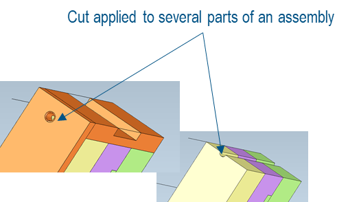 |
| View of assembly before and after cut |
Composite Tolerances
3D InterOp introduces capabilities to support the import of composite tolerances from NX files, enabling design and manufacturing end-users to utilize composite positional tolerancing with ease and precision.
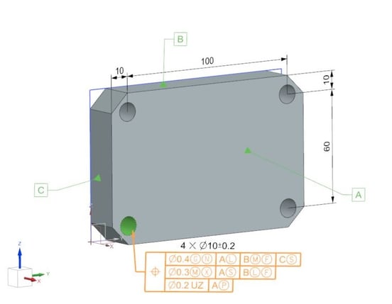
Composite positional tolerancing, as defined by GD&T/Model Based Definition standards, serves as a pivotal aspect of modern design and manufacturing. Composite tolerances provide a sophisticated framework for defining the location of feature-of-size patterns and establishing interrelations, both in terms of rotation and translation, among features-of-size within these patterns.
The unique strength of composite tolerance frames lies in their ability to impose stricter tolerances for orientation in the lower segments compared to the upper segment. This approach allows for fine-tuning in both positional and rotational adjustments, delivering precision in component placement and alignment. By providing a more precise means to position and orient pattern components, this feature empowers design, manufacturing, and metrology professionals to achieve previously unattainable levels of precision and accuracy.
| Example of hole pattern located by composite tolerancing with primary and secondary datums in the second segment. |
 |
|
Here, the Feature Relating Tolerance Zone Frame (FRTZF) is constrained in orientation within the limits of the Pattern Locating Tolerance Zone Frame (PLTZF). |
Consult Spatial today for additional details about 3D InterOp's new capabilities and file type support, or follow the link below to learn even more about the SDK.


CGM Polyhedra Introduces Lossless Compression for Streaming 3D Meshes
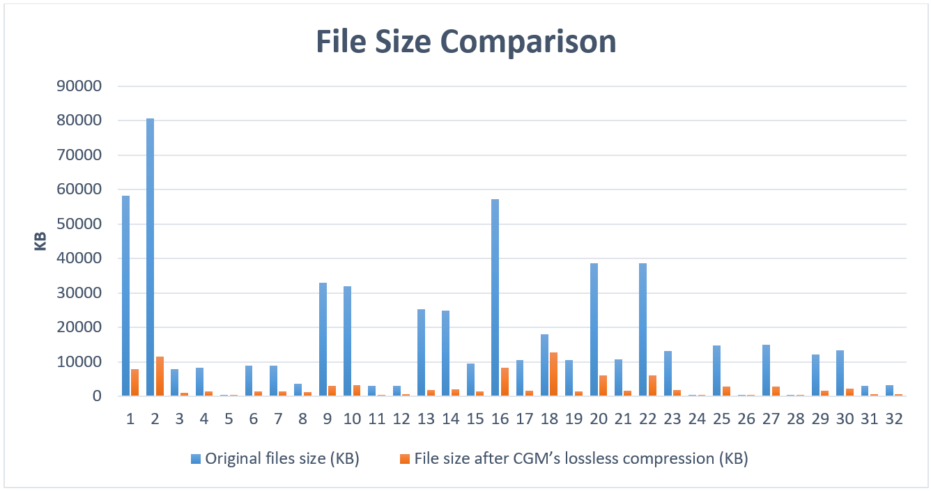
 New in 2024 1.0, CGM Polyhedra introduces advanced functionality allowing lossless compression of 3D meshes. When you build an ecosystem of applications on top of CGM Polyhedra, you can now optimize the way your data is stored and transmitted.
This new feature allows end-users to compress mesh files by 80-85% of their original size. For instance, a 553 MB file could be compressed to 87 MB while maintaining the data's integrity. In addition, end users have the flexibility to choose between two compression modes, balancing space-saving and performance considerations.
 |
Consult Spatial today for additional details about CGM Polyhedra's new capabilities, or follow the buttons below to learn more.

Void Extraction Capabilities For The 3D ACIS Modeler

In New in 2024 1.0, the 3D ACIS Modeler introduces an API for Void Extraction. Purpose-built for CFD (Computational Fluid Dynamics) and simulation workflows, this functionality automatically constructs solid bodies from open void regions. Such open void regions can include pockets, blind holes, open pipes, or any region with multiple openings. CFD application developers can now focus on their solver differentiators rather than develop common data preparation algorithms.
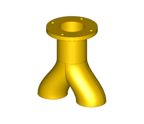 |
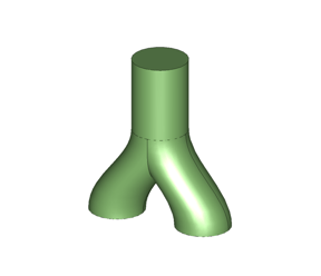 |
| Input | Output |
api_void_volume can extract voids from pockets, blind holes, or even through holes with multiple openings. This API can seamlessly transform these void regions into fully realized solid bodies. To further simplify access to the "api_void_volume" API, a new Scheme extension, "body:void-volume," has been implemented.
Consult Spatial today for additional details about ACIS Modeler’s capabilities, or follow the button below to learn more about the SDK.

Other Modeler Improvements
CGM Modeler & CGM Polyhedra
- The new CATICGMTopComputeTurningProfile operator calculates a polyhedral approximation of the spun profile of a part. This can help automate the setup for turning operations, such as figuring out the size of the cylindrical stock needed for lathe-turned parts.
- Automatic wire support generation has been enhanced to improve robustness and performance for additive manufacturing workflows.
- CGM Polyhedra adds support for sheet body thickening to create solids.
ACIS Modeler
- Based on customer feedback ACIS Modeler improves mid-sheet generation. The enhancements include:
- New APIs for retrieving progenitor information and managing associated data.
- A new 'offset_ratio' option that allows a mid-sheet to be generated at locations other than the geometric middle. This helps to model a variety of materials, since the neutral surface may not always be at the exact center.
- Stitcher enhancements have been made to support creating multiple bodies rather than a single body in cases where the resulting bodies are in contact with each other. This can be relevant for sheet metal manufacturing workflows.
- Reintroduction of the bridge between the 3D ACIS Modeler and the HOOPS Visualize HPS interface.
- Changes to comply with modern C++ 20 compilers
- Removal of NULL_REF from the interface.
- The return type of operator==and operator!= has changed from logical to bool in public classes such as curve, surface, and their derived classes.
Please visit Spatial's documentation website for specific technical details and documentation of these new improvements.
As part of our commitment to prioritizing the security and integrity of your advanced engineering software systems built upon Spatial technology, our team actively identifies and mitigates potential vulnerabilities using industry-standard tools, databases, and composition analysis software for identifying CVEs. This approach ensures confidence and resilience for you and your end users.
Other Highlights in 2024 1.0
3D InterOp: Refer to the 3D InterOp Release Notes for a complete list of updates
CGM Modeler / CGM Polyhedra: Refer to the CGM Modeler release notes for a complete list of updates
3D ACIS Modeler: Refer to the 3D ACIS Modeler release notes for a complete list of updates
3D Precise Mesh: Refer to the 3D Precise Mesh FAQs for more information