Take a fresh, new sheet of paper, and fold it in half, like you’re making a paper airplane. Place the folded paper on the table in front of you. What happens?
Most likely, the two halves don’t lie flat against each other. Even if you sharpen the crease, the top half will tend to lift away from the bottom half.
This is the phenomenon of springback—the tendency of a material, when bent, to try to return to its original shape.

Why Does Springback Compensation Occur?
Springback occurs in all materials. It’s mildly annoying if you’re folding a paper airplane, but imagine that you’re fabricating sheet metal parts instead: If you bend sheet metal to a specific angle, springback guarantees that the finished piece won’t stay in that shape. This can be a big problem in a manufacturing process, especially with more complex shapes.
Fortunately, springback is predictable; it’s a property of a material that varies by type of material, its thickness, the amount of bending applied, and the forming process (such as stamping or roll forming). Because it’s predictable, the tools and processes used in metal fabrication can be designed to overcome springback; this is called springback compensation.

Failure to analyze and compensate for springback can have serious consequences for manufacturers. Metal parts that spring back excessively after forming won’t have the right shape, which means that different parts won’t fit together properly during assembly. The result is poor-quality finished products, rework or repair of the nonconforming pieces, or even scrapping them entirely. All of these have negative impacts on customer satisfaction and profitability.
In this article, we discuss the causes of springback, various approaches to springback compensation, and their pros and cons.
Causes of Springback
Springback in a material has two main causes. One has to do with compressive and tensile forces at the molecular level, and the other involves the stress and strain properties of the material.
When you bend a piece of sheet metal, the molecules at the inside of the bend are compressed together, and those on the outside of the bend are stretched apart. The compressed molecules want to push themselves apart from each other, and the stretched molecules want to pull themselves back together. The result is springback.
From a stress-strain perspective, springback occurs according to the amount and type of bending and physical properties of the material. In an unbent piece of sheet metal, the atoms are arranged in such a way that the forces between them balance out and the material remains in a stable state. Bending the material a little causes the atomic forces to be out of balance, and when you let go of the material, the atomic forces push the material back to its original shape. This is called elastic deformation—the material returns to its original shape with no permanent change.
Now bend the material past its yield point, where the atoms rearrange themselves to a new stable state where the material doesn’t return to its original shape. This is called plastic deformation. Springback occurs because some of the atoms haven’t rearranged themselves and are still exerting elastic stresses to try to restore the original shape.
Springback can be influenced by both the bending angle and the bend radius; different bend radii can result in different amounts of springback. Imagine bending a piece of sheet metal around a pencil (small bend radius) versus bending it around a soup can (large bending radius). Because the material is not bent as sharply with a larger bending radius, the yield point of the material is harder to reach, and springback is more pronounced.
Springback Compensation Strategies
To achieve the desired shape in sheet metal fabrication, springback must be anticipated and compensated for. Some techniques are available to shop-floor personnel during the sheet metal forming process:
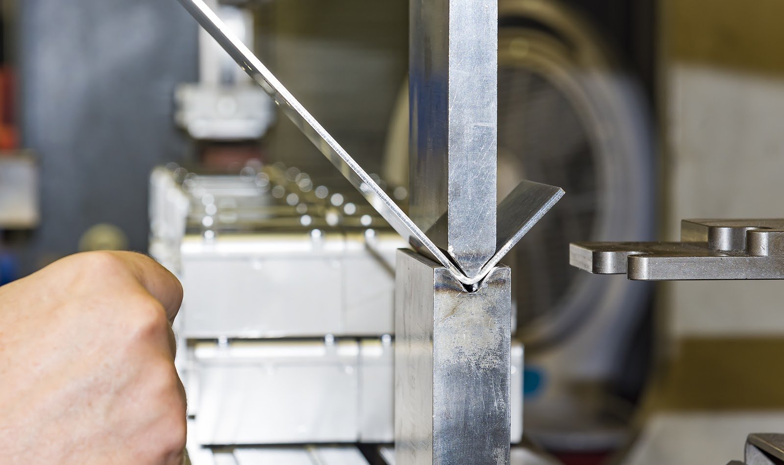
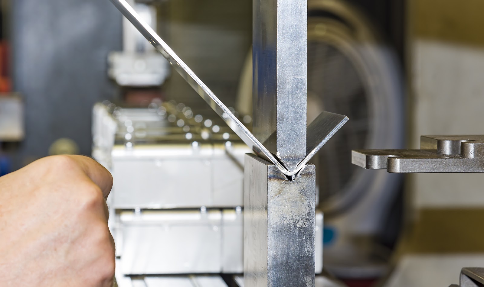
- Overbending: In this technique, the material is bent past its designed angle so that the springback brings the material to the desired angle (the bent angle). The amount of overbending (the bending angle) can be determined using mathematical formulae that involve the thickness of the material, the desired angle, and physical material properties (which vary, for example between soft and high-strength steels and between steel and aluminum, for example). When using a press brake, overbending is achieved by the air forming process, in which the punch has a smaller angle than the die, resulting in an air gap between the material and the bottom of the die.
- Re-bending: Springback can be overcome simply by repeatedly bending the material. However, doing so can result in metal fatigue, where the material is weakened or damaged at the point of bending.
- Increased forming force: The force exerted on the material during bending can be increased to overcome springback. When using a press brake machine, this means pushing the material all the way to the bottom of the die (a process known as bottom forming). However, this approach requires more energy and may require more force than a given machine can provide; in addition, the increased pressure can weaken or damage the material.
An additional disadvantage of relegating springback compensation to the shop floor is that it can be time consuming (reducing productivity) and inaccurate (if the calculations are wrong). Further, because of differences from machine to machine and from piece to piece, springback compensation during sheet metal forming can be a frustrating and expensive exercise in trial and error for each fabricated item.

CAD Springback Compensation
A better approach is to properly design the forming parts (punches, dies, and other form tool features) so that the operators don’t have to perform piecewise springback compensation.
Designing forming tools for springback compensation using computer-aided design (CAD) tools has the advantage of enabling testing of the design by simulation before making and using the tool on the shop floor. In this way, the tool design can be optimized before the forming tool parts are made, thereby reducing wasted time and materials.
However, simulating springback in CAD has its own challenges. First, the physical properties of the sheet metal (such as minimum bend radius and elastic modulus, which determine the “springiness” of the material) must be known. This means having the proper CAD design library for the material.
In addition, CAD simulation of a dynamic process such as metal forming necessarily involves a method called finite element analysis (FEA), which slices and dices the simulated material into small virtual pieces (the “finite elements”) and estimates the interactions of the forces among the elements. For greatest accuracy, the elements must be made as small as possible, which increases the number of elements and therefore increases the computational power required to analyze them. Designers must strike a balance between accuracy and analysis time.
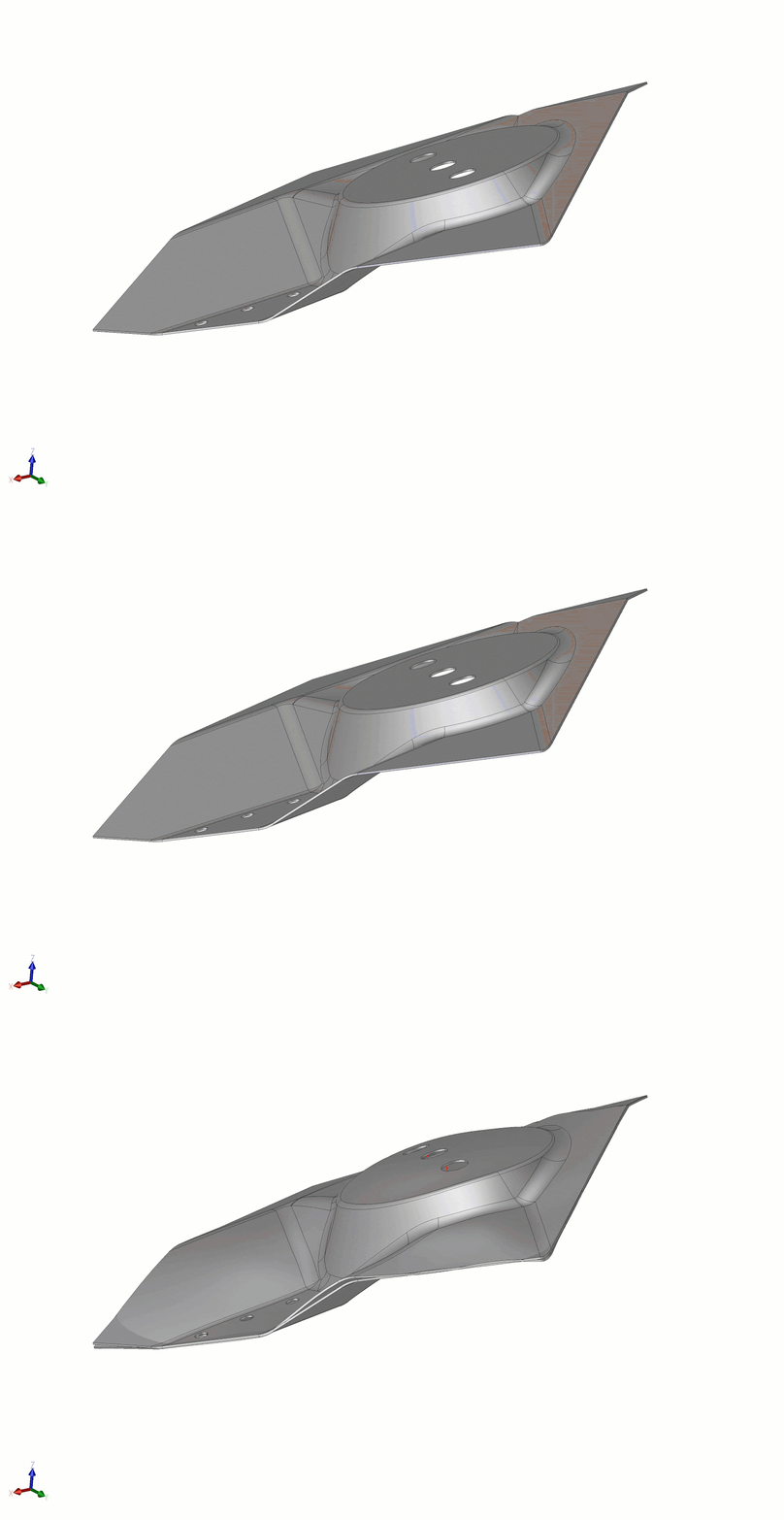
Another challenge is that the resulting deformation from such an FEA run is a field that corresponds directly to the mesh or the FEA elements. And not to the original CAD model. One recent development in some CAD systems to deal with this is known as CGM (Convergence Geometric Modeling) morphing operator, which are designed to apply these deformation vector fields to the CAD model. Thus closing the loop of design optimization to counter springback for a given material, shape, and forming process.
Although springback is unavoidable, with proper design and planning, it can be compensated for, resulting in the perfect shape every time.


.jpg?width=450&name=Application%20Lifecycle%20Management%20(1).jpg)


