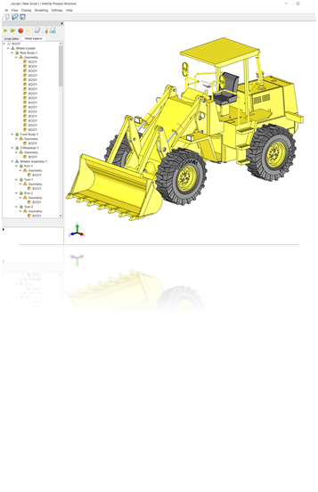
Effective computer-aided design (CAD) and computer-aided manufacturing (CAM) programs include the following main components: the user-interface (UI) and the application logic.
In turn, the application logic of the CAD/CAM software itself consists of the following parts:
- the database;
- 3D visualization suite;
- mesher;
- 3D modeler;
- and the 3D data translation suite.
In this post, we’ll take a look at the specific capabilities you need out of each application logic component in order to build a fully capable CAD/CAM system.
Application Logic
In short, the components of a CAD system’s application logic are the most important -- and the most difficult -- software parts. However, they’re the components that not only make CAD suites work, but differentiate more capable, high-quality suites from substandard ones.
Database
The database is a standard software component for all programs, not just CAD. Your application
will control the database through a database management system (DBMS).
3D Modeler
The 3D modeler is a critical component of CAD. It should allow you to create, modify and query geometric representation of objects for visualizing, simulating, or analysing them.
Your 3D modeler should, for a start, provide the following:
Polyhedral Modeling
In addition to B-Rep, the 3D modeler should offer the ability to represent geometry in triangular mesh form, especially from STL, 3MF and other comparable data sources.
Polyhedral modeling is important for a number of industries, especially in health and building information modeling (BIM). So, for example, in medical design work the shapes are usually more organic. By trying to model this data in B-Rep form, you run the risk of building too much topology or spatial relations , in turn, taxing the designers/engineers’ hardware and software.
In contrast, polyhedral modeling is less taxing on the system and allows for more flexibility in certain workflows where maintaining these complex spatial relations and properties is not as important. The idea is to make the shape less resource intensive.
Error Checking and Diagnostics
The modeler should be able to find anomalies or issues in the design that could cause in functional failure. It should also be able to provide smart diagnostics that can then be used to improve the design, iteratively.
Checking Operations
Your 3D modelers should equip your users to identify issues in need of potential correction, e.g., duplicate or redundant geometries, sliver triangles, intersecting edges, etc.
Cleanup Operations
These are healing functions that help the user save time when fixing potential issues. Your 3D modeler should provide stitching, repair, removal, and hole covering operations.
Query Capabilities
With query capabilities, your users will be able to examine CAD models in detail so as to find and resolve potential issues earlier in the design process. They’ll need distance queries, clash detection, closure, ray-fire as well as volume, area, and mass property queries.
The above are just a few of the capabilities your 3D modeler needs for most workflows, but you should also think about adding planar and multi-planar slicing, deformation and boolean operations.
Defeaturing
It should recognize feature types (e.g., holes, pads, pockets, logos, etc) and be able to remove features. The 3D modeler should also allow for model simplification. This is especially important if you are building a simulation system as, more often than not, you will want to simplify your models as much as possible to enable performant simulations.
See How Simerics Delivered on All of Its CAD/CAM
Feature Requirements Using Spatial’s SDKs
3D Data Translation
The next component is a 3D data translation suite. This allows you to import CAD/CAM files of different formats for data re-use and interoperability between different teams, workflows, etc.
A fully capable 3D data translation suite will allow the end-user to import a CAD or CAM file’s product or assembly structure, tessellated geometry, exact or B-Rep geometry, and meta-data identifiers.
Meshing
Your CAD suite should offer the ability to create a mesh model, i.e., models with polygonal representation (e.g., triangles, quadrilaterals etc) but without mass properties. This is a necessary part for software-based simulation, such as computational fluid dynamics (CFD) or Computer Aided Engineering (CAE).
Specific capabilities of your meshing suite should include:
- Surface Meshing
- Mesh Cleanup
- Volume Meshing
- Mesh Adaptation.
Visualization
The 3D visualization suite serves as the back-end engine for your CAD/CAM software’s 3D modeling and 3D data translation capabilities. It should support proven frameworks such as OpenGL and Direct 3D as well as integrate into the components we described above.
User Interface (UI)
This is essentially the part of your CAD/CAM application that the end-user sees, i.e., the front -end user experience (UX). However, while important, the UI/UX is the tip of the iceberg, so to speak, of the application. But to provide a first-in-class experience, you need each underlying component for generating, editing, and visualizing the models.
Ensure Your CAD/CAM Systems Offer These End-User-Required Capabilities:
- Why 3D Data Translation is Essential for Supporting Today’s Engineering Workflows
- How 3D ACIS Modeler Improves the Quality of Translated 3D Data
- 3 Functionalities Required to Translate 3D CAD Data
Overall, the challenge for independent software vendors (ISV) is developing and maintaining each of the CAD/CAM suite’s components. Not only do you need a large amount of software development resources, but you need core engineering expertise as well.
This is an unrealistic expectation for every ISV, which is why out-of-the-box (OOTB) solutions already containing those components are critical. Leveraging OOTB suites allows you to not only deliver the exact capabilities end-users expect, but cut your own development time and focus on differentiation (e.g., perfect the UI/UX) instead.
Spatial provides every component you need for a world-class CAD/CAM suite, including 3D data translation (3D InterOp), 3D modeling (3D ACIS & CGM Core Modelers), meshing (3D Precise Mesh), and 3D visualization (HOOPS Visualize). Contact us today and evaluate our SDKs.


.jpg?width=450&name=Application%20Lifecycle%20Management%20(1).jpg)


