

Recently I was asked by a customer how to render a 3D visualization model translated from a CAD file by Graphical 3D InterOp (see ref 1 below.) The customer is using HOOPS so the quick answer was to use our bridge libraries which connect our products together and sure enough there is a 3D InterOp/HOOPs bridge for precisely this purpose. However I thought that I would really like to know how the data gets passed between the different components, especially as I had a small test application I had used a while ago and I never got the display to be as good as that generated by the bridge. (The bridge is actually shipped as source, so the code is available if you want to take a look at it.)
The first thing I needed to understand was the format of the data being supplied by Graphical InterOp (I am just going to concentrate on the rendering information for the faces in a model.) Each face in the model gets described by a set of collections of triangles. The data consists of vertex positions for every vertex in the face, vertex normal at each vertex and a description of the way the vertices are connected.
Triangles are described by the indices of the vertices into the vertex position array, as a simple list of triangles or in optimized form as TriStrips or TriFans.
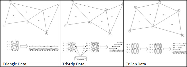
This is all pretty standard and the descriptive information is in the InterOp documentation, but the steps to render the triangles into HOOPS have some subtleties that I had overlooked in my early attempt.
First I knew that I wanted to make shells in HOOPS because they would support the nice shading and lighting effects with good continuity between the triangles, however in InterOp the data for the face is presented as a series of sets of Triangles, TriStrips or TriFans and to get the shading across the face I needed to combine these into a single shell for the entire face.
Second by combining these shells I actually make the process more efficient as I only present the vertex positions to the HOOPS functions once for the face instead of once for each set of triangles.
Thirdly I found that I could insert TriFans into HOOPS using the same function as TriStrips (HC_Insert_Shell_By_Tristrips) except that I had to set the number of vertices in the TriFan data to be minus the actual number, then HOOPS would interpret the TriFan correctly. So even though HOOPS does not support TriFans internally, it does allow shells to be defined by TriFans as input data.
Finally for shading purposes HOOPS can calculate normal vectors in a shell from the vertex positions, however InterOp is providing me with these normals from the actual model. Using the normals from InterOp gives improved continuity at face boundaries.
With these in mind I wrote some code to get the data into the HOOPS database:
// Iterate through the triangle sets in the face
std::vector<int> face_list_indices;
SPAIopVisuPolygonIter polygon_iterator = currentFace.GetPolygonIterator();
while( polygon_iterator.Next())
{
  // Get the current triangle set
  SPAIopVisuPolygon current_polygon = polygon_iterator.Current();
  SPAIopVisuPolygonType polygonType( SPAIopVisu_PolygonType_Unknown );
  const int* p_polygon_indices = NULL;
  int polygon_index_count = current_polygon.GetPolygonIndices(p_polygon_indices, polygonType );
  int polygon_index;
  switch ( polygonType )
  {
  case SPAIopVisu_PolygonType_Triangle:
    for ( polygon_index=0; polygon_index<polygon_index_count/3; polygon_index++ )
    {
      face_list_indices.push_back(3);
      // divide by 3 as HOOPS indexes by point (i.e. 3 floats)
      face_list_indices.push_back(p_polygon_indices[polygon_index*3]/3);
      face_list_indices.push_back(p_polygon_indices[polygon_index*3+1]/3);
      face_list_indices.push_back(p_polygon_indices[polygon_index*3+2]/3);
    }
    break;
  case SPAIopVisu_PolygonType_TriStrip:
    face_list_indices.push_back(polygon_index_count);
    for ( polygon_index=0; polygon_index<polygon_index_count; polygon_index++ )
    {
      // divide by 3 as HOOPS indexes by point (i.e. 3 floats)
      face_list_indices.push_back(p_polygon_indices[polygon_index]/3);
    }
    break;
  case SPAIopVisu_PolygonType_TriFan:
    face_list_indices.push_back(-polygon_index_count);    // Negative for TriFan
    for ( polygon_index=0; polygon_index<polygon_index_count; polygon_index++ )
    {
      // divide by 3 as HOOPS indexes by point (i.e. 3 floats)
      face_list_indices.push_back(p_polygon_indices[polygon_index]/3);
    }
    break;
  }
}
// Get the face points and normals
const float* p_face_vertices = NULL;
int face_vertex_count = currentFace.GetVertices( p_face_vertices );
const float* p_face_normals = NULL;
int face_normal_count = currentFace.GetNormals( p_face_normals );
// Create the shell
HC_KEY shell_key = HC_Insert_Shell_By_Tristrips (face_vertex_count, p_face_vertices,
face_list_indices.size(), face_list_indices.data(), 0, NULL);
HC_MSet_Vertex_Normals(shell_key, 0, face_normal_count, p_face_normals);
To improve the appearance I used Phong shading which gives smooth interpolation of colors over the faces with nice specular highlighting effects. This is achieved in the Phong shading algorithm by interpolating the normal vectors across the triangles, again making use of the normal information I had supplied from InterOp. I set this option on the main HOOPS segment that held my model.
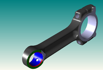
Here is one of our demo parts that has been rendered using the code.
In conclusion, I was pleased with the images I generated, the code I wrote was simple and actually more efficient in terms of data than my original attempt. I would recommend using the bridge code as a much quicker implementation though!
.png?width=450&name=AdobeStock_188705270%20(2).png)


.jpeg?width=450&name=AdobeStock_289023609%20(2).jpeg)


.jpg?width=450&name=Application%20Lifecycle%20Management%20(1).jpg)


