
2023 1.0 Introduces Polyhedral Modeling, Further Extends Automation and Interoperability in Manufacturing, Elevates Cross-Department Collaboration, & More
Release Highlights:
- Process Mesh Data in Your ACIS Application with ACIS Polyhedra
- Further Extend Automation in Manufacturing with CGM
- Enhance Manufacturing Processes with 3D InterOp
- Efficiently Collaborate Across Disciplines in Building Information Modeling and Collaborate on Digital Twins with 3D InterOp
- Other Highlights in 2023 1.0
Process Mesh Data in Your ACIS Application with ACIS Polyhedra
Meshes are often ubiquitous in workflows that involve organic shapes, such as medical, dental, or artistic design applications, or in architectural, engineering, and construction (AEC) or plant-/vessel-design workflows that involve large data sets. Moreover, meshes are increasingly popular for traditional CAD workflows and manufacturing industries like robotics, computer-aided manufacturing, and additive manufacturing.

ACIS-based applications can now import and query meshes, perform any necessary healing and decimation, create mesh bodies, and perform basic Boolean operations such as unite and subtract on these imported mesh bodies. Such functionality extends ACIS into the realm of meshes and provides ACIS customers even more flexibility and performance for different types of geometric data.
For example, ACIS-enabled dental applications can now import meshes of gingiva and teeth from intraoral point scans, query the meshes for anomalies such as gaps or incorrect normal, heal any anomalies and perform downstream Boolean operations such as uniting meshes of gingiva and teeth into one model.

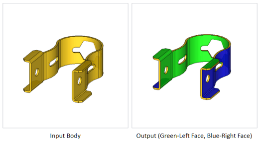
Automated Face Pair Detection for Mid-Surface Generation
Also in 2023 1.0, ACIS has now automated face pair detection for mid-surface generation. This improves the ease of use of the recently released mid-surface operator and enables more efficient CAE workflows.
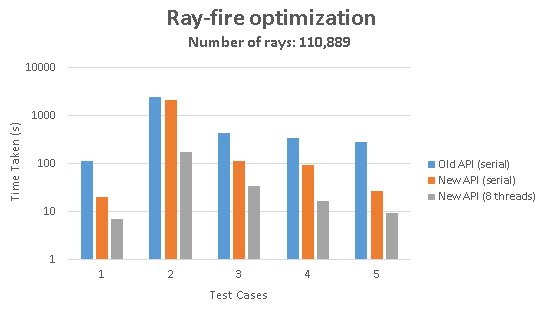
Ray-Firing Performance Improvement – Now 100x Faster!
Additionally, ACIS ray-firing performance has drastically improved with this new release. Thanks to multi-threading and multiple ray firing, ray-firing workflows are sped up by up to 100x than previous versions. Optical design and robotic painting workflows, where multiple rays have to be fired and performance is very important, benefit greatly from this improvement.
Consult Spatial today for additional details about ACIS Polyhedra’s capabilities, and stay tuned for an upcoming webinar about ACIS Polyhedra early next year.


Further Extend Automation in Manufacturing with CGM Modeler and CGM Polyhedra
New in 2023 1.0, CGM Modeler (CGM) and CGM Polyhedra introduce functionality for the automatic creation of supports for additive manufacturing workflows. In particular, CGM now offers the ability to automatically compute support zones between the part and print tray as well as generate both non-solid and solid (volume and cone) type supports in these zones. Furthermore, the existing functionality to create wire supports has been updated.
Up until now, CGM Modeler has offered functionality to create wire supports for 3D printing workflows. Now, this functionality has been extended to include the computation of support zones as well as the creation of volume and conical supports. This new functionality enables faster development of additive manufacturing applications while allowing users of such applications more flexible and robust workflows to quickly prepare parts for 3D printing.
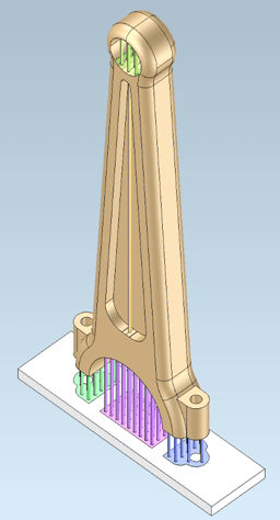
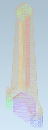
Consider a new optimized lightweight part that replaces a heavy part in an assembly – for example, the connecting rod of an internal-combustion engine for an automobile. Traditional manufacturing methods are employed to fabricate the connecting rod, including forging and milling. However, the lightweight connecting rod has an internal honeycomb lattice that mandates the use of 3D printing.
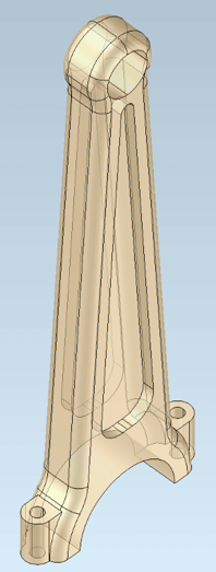  |
| Connecting Rod solid and lightweight |
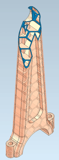
Before the lightweight connecting rod is printed from powdered metal, it must be prepared by adding supports. The supports not only support the part during printing but also conduct heat away from the part. CGM Modeler and CGM Polyhedra greatly simplify the process of adding supports.
 |
| Connecting Rod Support Zones |
First, CGM Modeler automatically computes support zones that project between the part’s external faces and the printing tray.
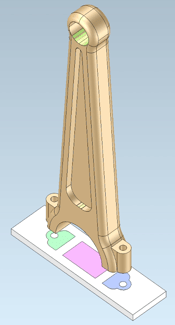
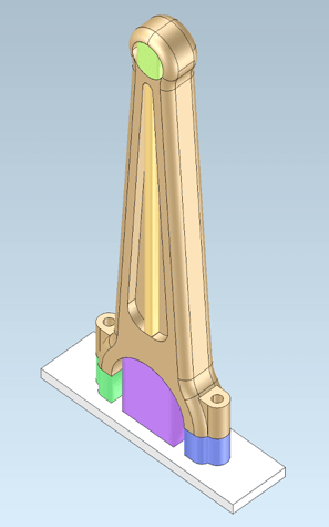
Second, these support zones guide the subsequent and automatic creation of volume supports and conical supports. Volume supports are arbitrary volumes that fill the perimeters of the support zones and the spaces between the support zones on the tray and the corresponding part faces. Conical supports are cones that are contained within the perimeters of the support zones and extend between the support zones on the tray, and the corresponding part faces. The conical supports’ diameters and spacing can be easily adjusted, yielding both finely and coarsely spaced supports.
|
|
|
|
Volume Supports |
Conical Supports |
Third, CGM Modeler slices the supports. The slices can be passed to the overlying application to compute toolpaths and, ultimately, NC-code to print the part.
 |
| Connecting Rod Sliced |
The new functionality to compute support zones and easily create both volume and conical supports is a highlight for 2023 1.0 and underscores the ability of CGM Modeler to enable ease of use for 3D printing workflows.
Reach out to your Client Executive or Technical Account Manager for more details about support functionality for 3D printing applications in CGM Modeler. In addition, register for our webinar below for a demonstration of supports for 3D printing within AGM.

Consult Spatial today for additional details about CGM's new capabilities, or follow the buttons below to learn more about the two SDKs.


Enhance Manufacturing Processes with 3D InterOp

New in 2023 1.0, 3D InterOp introduces capabilities to read weld geometry from Creo® files and read part-level PMI in STEP AP242 assembly files.
Importing weld designs allows applications to seamlessly integrate critical weld geometry and data into downstream workflows. This data is important to ensure performant designs and efficient manufacturing processes as well as prepare the control and measurement of manufactured parts per quality standards.
Spatial continues to support collaboration with model-based design (MBD). Reading part-level PMI in STEP AP242 assemblies permits fast analysis of complex assemblies and enhances the process of manufacturing individual parts in assemblies.
Application users collaborating with STEP AP242 files benefit from features such as views, notes, dimensions, GD&T, and associativity to the underlying geometry. Application users also directly benefit from cost-effective manufacturing processes on STEP AP242 assembly files.
Efficiently Collaborate Across Disciplines in Building Information Modeling and Collaborate on Digital Twins with 3D InterOp
New in 2023 1.0, 3D InterOp introduces capabilities to import base points and survey points in Revit® files.
With 3D InterOp’s extension of its Revit® Reader, users can now import support shared coordinates, including project base points and survey points. Importing such points expands collaboration across disciplines and enables the faster integration of Revit projects into BIM (building information modeling) collaboration workflows.
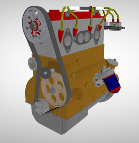
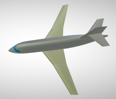
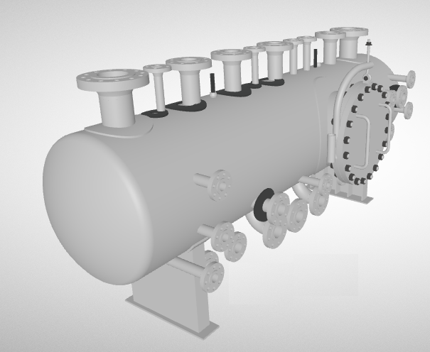
Also in 2023 1.0, 3D InterOp introduces the capability to write glTF™ data for visualization workflows. This capability allows you to transform data to glTF™, a compact, cross-platform, and web-friendly output for your application workflows, and reach market opportunities with run-time optimized 3D assets.
The glTF™ format has been described by its creators as the “JPEG of 3D data”. Gaining the ability to write glTF™ data is a great addition to workflows that consume 3D engineering data within virtual experiences and enable digital twins of products, production systems, and facilities.
 |
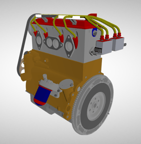 |
| GLTF File of an Engine | GLTF file of an Engine |
|
|
|
| GLTF File of an airplane | GLTF File of a tank |
Consult Spatial today for additional details about 3D InterOp's new capabilities and file type support, or follow the link below to learn even more about the SDK.

Other Highlights in 2023 1.0
3D InterOp:
- Export of geometry as trimmed surfaces in IGES files
- Retrieval of object properties as user-defined attributes (UDA) from Revit files
- Read MKS (meter, kilogram, second) units of properties from IFC files
- Import polygonal meshes as visualization from Rhino® files
- Memory footprint improvement of B-REP imports
- Enhancements to STEP and IGES geometry conversions performance in CGM
- Improvement to DXF/DWG 2D reader performance
- 3D InterOp extends its new functionality by supporting a range of formats as well as Mac ARM platforms. *Mac ARM platform support will come in a hotfix after this release*
Refer to the 3D InterOp Release Notes for a complete list of updates
CGM Modeler/CGM Polyhedra:
- CGM Polyhedra now supports polyhedral inputs for HLR
- New operator that provides high-level healing for improved offset operations
- New operator to calculate the maximum gap between edges or the Hausdorff distance.
Refer to the CGM Modeler release notes for a complete list of updates
3D ACIS Modeler:
- Improved Multi-Threading Infrastructure: Use ACIS Thread Manager from Worker Thread
- Enhanced error information for Local Operations APIs
- MAC ARM platform support
Refer to the 3D ACIS Modeler release notes for a complete list of updates
3D Precise Mesh:
- The 2.15 version of MeshGems contains improvements related to the meshing quality and robustness and various corrections.
- Both ACIS and CGM bridges now support MeshGems versions 2.4 to 2.15.