


One of the important uses of 3D models in the building information modeling (BIM) process is as inputs to analysis. There are many different areas of building analysis, the most obvious ones being structural analysis for static loads, for dynamic loading under winds, or the stress resulting from earthquakes
The package, EnergyPlus, uses a text-based input file to describe the model and conditions to be analyzed. This file is read in and used to produce an Excel spreadsheet showing the requested outputs. Additionally, the program can produce a DXF model of the input, which is a nice touch to help visually verify the inputs. The input file describes the geometry of each object in the building as a set of four planar vertices representing the outside face of the object.
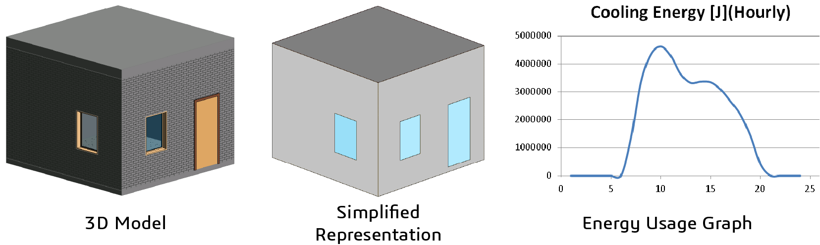
My task was to find the external face of each of the components that made up my 3D model and extract the coordinates of the four vertices. Each wall was defined as a rectangular profile extruded from the floor to the ceiling. The convention used was that the wall had its own coordinate system, with the origin at the lower vertex of the inside wall, with the X direction along the wall and the Y direction pointing towards the outside.
Once constructed the wall is transformed into the object space of the building. To get the external face of the wall, I had to find the centroid of the wall and fire a ray towards the outside — the resulting hit was an outside face. Not surprisingly this scheme almost worked, but I got a warning in the output
The Zone="ZONE ONE" is not fully enclosed
When I looked at the DXF data for the simulation, this error was easy to diagnose. The outside faces of my model do not all meet up because the roof and the floor have additional side faces that are also external. To get around this issue, I could use the internal faces, but then I would feel cheated out of some of the volume of my house. Then it occurred to me that using the geometry of the objects as my inputs, I could simply unite the walls, floor
In conclusion, I thought I would simply be querying the geometry to get the inputs for my simulation but was surprised that I needed to perform geometric operations as well to satisfy the input requirements for the analysis. The analysis package was straightforward to use for this very simple example, although I found that there were many other inputs I had not considered, such as layers of insulation. But additional components like heaters and air conditioners will have to be the subject for another time.
Learn More:
- Clashing Geometry in BIM Datasets
- Vertex Systems — 30 Years of BIM Innovation
- Advanced 3D Modeling Unites a Multi-disciplinary Approach to Harbor Design
- Leveraging 3D Software Development Toolkits as Buildings Move into the Digital Age
- Innovative 3D Uses for AEC/BIM and supporting Advanced Workflows for Additive Manufacturing
.png?width=450&name=AdobeStock_188705270%20(2).png)


.jpeg?width=450&name=AdobeStock_289023609%20(2).jpeg)


.jpg?width=450&name=Application%20Lifecycle%20Management%20(1).jpg)


