

Accurate boundary-layer resolution is one of the most critical factors in fluid-flow simulations. Whether the goal is predicting drag, heat transfer, separation, or near-wall turbulence, the quality of the boundary-layer mesh directly determines the reliability of the results.
Yet generating robust boundary layers remains a persistent challenge, especially when working with complex or imperfect geometry.
Why Boundary Layers Matter
In fluid dynamics, the boundary layer is the thin region adjacent to solid walls where velocity gradients are steep and viscous effects dominate. Capturing this region correctly is essential for:
- Accurate wall shear stress and friction predictions
- Reliable turbulence modeling
- Correct heat transfer calculations
- Stable convergence of the solver
A poor boundary-layer mesh often leads to non-physical results, excessive numerical diffusion, or solver instability, regardless of how refined the rest of the mesh may be.
The Geometry Comes First
Before discussing meshing strategies, let’s emphasize the importance of high-quality geometry in reliable boundary layer generation.
Small gaps, sliver faces, poorly stitched surfaces, or inconsistent topology often prevent boundary-layer extrusion or cause layer collapse. Even geometry that is technically valid can still be problematic if it contains unnecessary complexity, such as tiny edges or fragmented faces near walls.
For this reason, geometry preparation and healing play a crucial role upstream. Ensuring watertight models, consistent surface definitions, and clean topology significantly increases the quality of boundary layers. For certain edge cases, the pre-processing can be manual, tedious and time consuming, requiring robust and automatic geometry pre-processing capabilities.
In addition to the dedicated mesh healing feature, Spatial’s Convergent Surface Mesher (CSM) includes embedded automatic CAD pre-conditioning that offers fast clean-up of various CAD artifacts such as simple overlaps, gaps, duplicated patches, missing topology. This helps generate high quality surface mesh and input to Convergent Volume Mesher (CVM) for robust and reliable boundary layer generation.
👉 To support the industry's variety of meshing needs, Spatial offers Convergent Surface Mesher (CSM) and Convergent Volume Mesher (CVM).
Furthermore, Spatial modelers - CGM Modeler and 3D ACIS Modeler - offer end-to-end workflows for pre-processing CAD data for simulation.
Structured Layers Near the Wall, Unstructured Away from It
The most widely adopted and reliable approach for high quality mesh is a hybrid meshing strategy:
- Structured or semi-structured layers near the wall, typically prismatic or hexahedral elements, aligned with the surface
- Unstructured tetrahedral or polyhedral elements in the core flow region
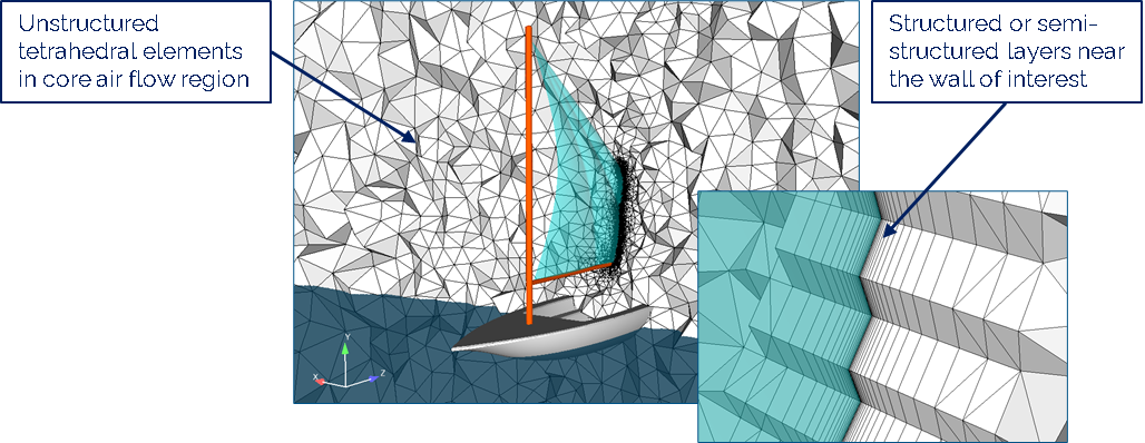
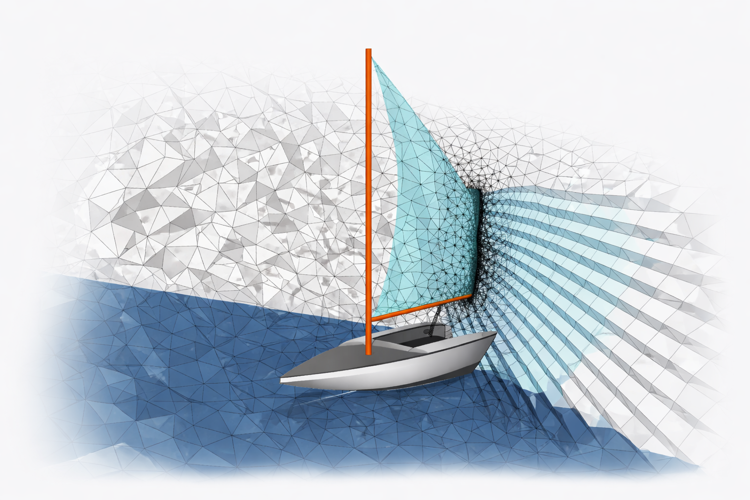
CFD Hybrid mesh strategy using CVM: Structured boundary-layer mesh is generated near the sail and wall surfaces to resolve near-wall flow, transitioning to unstructured tetrahedral elements in the core region for aerodynamic analysis.
This approach combines the accuracy of structured layers where gradients are strongest with the flexibility of unstructured meshes in complex flow regions.
Key parameters must be carefully controlled:
- First-layer thickness
- Growth rate between layers
- Number of layers to fully resolve the boundary layer
A smooth mesh transition between the boundary layered region and the core region is essential to avoid numerical artifacts.
Combining Boundary Layers and Hex-Dominant Meshing
To balance performance and accuracy in CFD simulations, the hybrid meshing strategy discussed above can be further extended. To boost downstream performance while maintaining accurate boundary-layer resolution, the core volume is filled with less expensive hexahedral elements. Different element types are used to efficiently manage the transition zones between regions, as shown below. This approach significantly reduces the total number of generated elements, enabling faster simulation times and quicker design iterations.
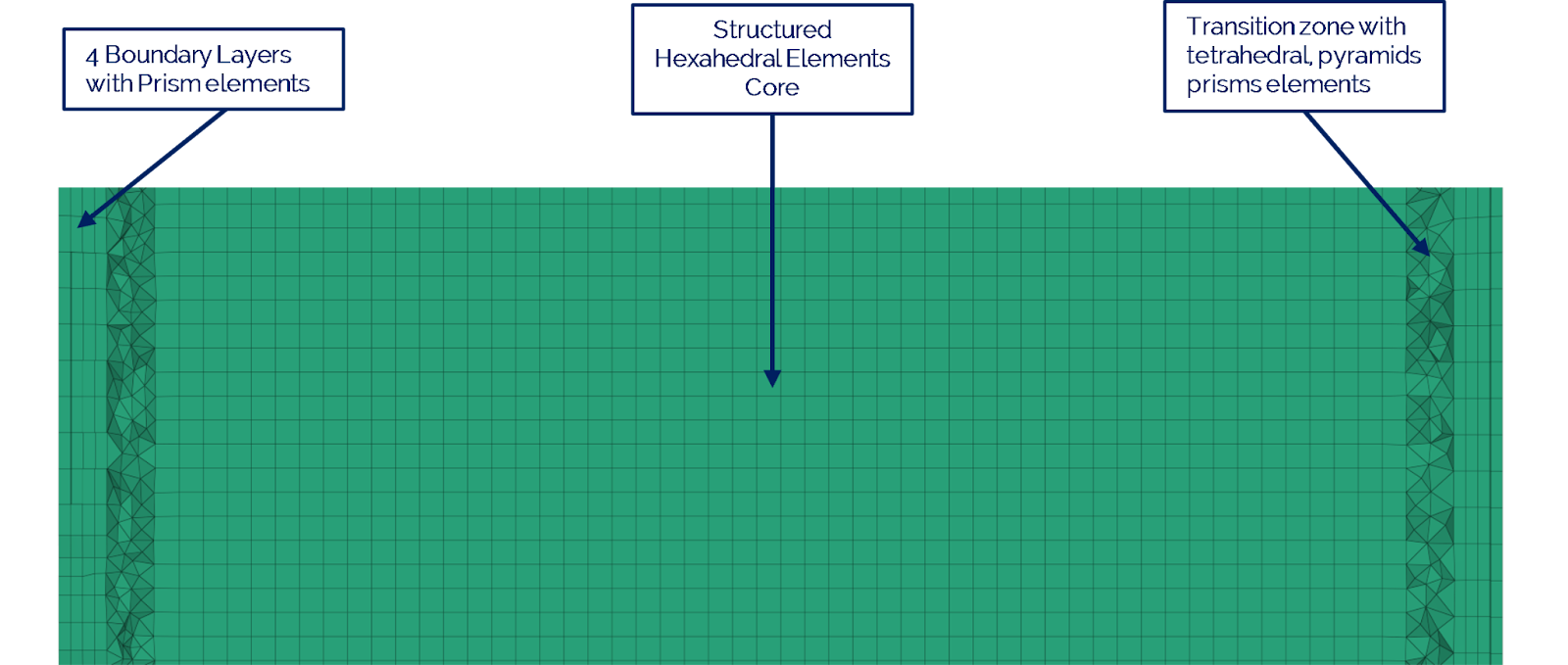
CFD Hybrid mesh strategy using CVM: Structured boundary-layer mesh is generated near the wall to resolve near-wall flow, transitioning to structured Hexahedral elements to significantly reduce the total number of elements generated.
There is no single boundary-layer strategy that universally fits all CFD simulations. The most effective approach depends on the specific physics being modeled, including the flow regime and turbulence formulation, the quantities of interest (e.g., drag, heat transfer, separation), available computational budget, and the quality and complexity of the underlying geometry.
Spatial’s CSM/CVM provides the flexibility to tailor boundary-layer generation and hybrid meshing strategies to each simulation’s requirements - enabling robust near-wall resolution, efficient core meshing, and controlled transitions - while balancing accuracy, performance, and geometric robustness for demanding fluid-flow applications.
Spatial’s Perspective: Balancing Accuracy, Robustness and Performance
From Spatial’s perspective, robust boundary-layer generation begins well before meshing. High-quality, well-healed geometry is fundamental to enabling reliable and automated meshing workflows.Spatial’s meshing technologies, tightly integrated with CGM Modeler and 3D ACIS Modeler, are engineered to streamline geometry preparation and boundary-layer generation - reducing manual intervention and minimizing geometry-driven failures so simulation teams can focus on resolving the underlying physics.
As simulation workflows grow in scale, complexity, and automation, strengthening geometric robustness upstream followed by fully-conformal hybrid meshing remains one of the most effective strategies for improving boundary-layer fidelity, solver stability, and overall simulation performance.

.jpg?width=450&name=AdobeStock_487440650%20(1).jpg)


