

3D Meshing: Best practices for Modern Simulation Workflows
Summary
- Introduction
- Understanding Meshing in CAE Workflows
- Examples of Solver Constraints
- Meshing Technology at Spatial
- Meshing Best Practices
- Advanced Meshing Workflows
- Integrating High-Quality Simulation-Ready Meshes
- About Spatial
Introduction
3D meshing capabilities are essential to Computer Aided Engineering (CAE) workflows because they convert complex geometry into finite elements that can be analyzed for structural, thermal, and fluid performance. This step ensures accurate simulation results by enabling engineers to model real-world behavior with precision, forming the foundation of reliable CAE analysis.
In this post, we’ll recommend best practices for 3D Meshing, explore different meshing workflows, and introduce Spatial’s meshing solutions. Spatial meshing SDKs facilitate seamless simulation integration in CAE applications and can enhance simulation workflows for application developers.
Before we dive in, if you would like to gain a deeper understanding of meshing, visit our glossary page on mesh generation.
Understanding Meshing in CAE Workflows
A CAE mesh connects your CAD data to the analysis application. It is a model discretization that meets the mathematical requirements of the targeted numerical solver or analysis application. Meshing enhances CAE workflows, offering control, accuracy, and performance in simulations.
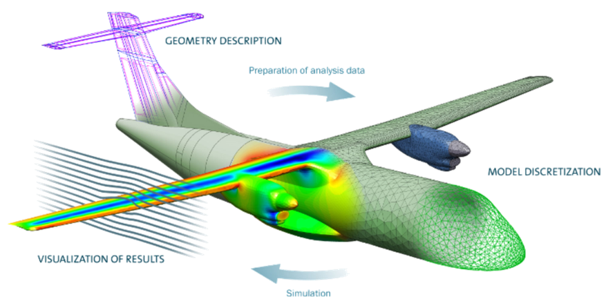
Four-step simulation workflow:
- CAD & Geometry Preparation - Importing, modifying, and pre-processing geometry.
- Simulation Preparation - Mesh generation and boundary condition setup.
- Simulation Execution - Solver computation based on numerical equations.
- Results Analysis & Visualization - Processing data for validation and decision-making.
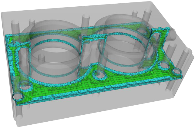
Caption: Example of a CAD model with meshing
This meshing workflow is the critical link between the geometry and the solver. It ensures the mesh generation process is well integrated and produces reliable results tailored for the solver. A mesh suitable for a CAE application is a special type of tessellation. The type of mesh suitable for CAE is not the same as a tessellation for graphical applications, not the same as a point cloud scan, and not any model tessellation. The solvers in CAE are modeling complex physical phenomena. The numerical equation approximations that are implemented in solvers rely on mathematical constraints that have to be respected to ensure accuracy in results.
Learn more about how Spatial SDKs solve challenges in the CAE industry.
Importance of Meshing
Meshing acts as a critical link between geometry and solvers. A well-integrated meshing process ensures accurate results, making it tailored to solver requirements. Different mesh types exist for various applications (e.g., rendering, engineering scans), but CAE requires highly controlled meshes for accuracy.
Examples of Solver Constraints
All solvers have very different constraints regarding the type of mesh they support to get meaningful results. Below are examples of the need to respect mathematical constraints.
Finite Element Analysis (FEA) Validation—Requires a consistent tessellation across an entire geometry in order to properly observe the convergence towards a solution when generating increasingly refined meshes.
Related read: What is FEA?
CFL Condition for Finite Difference Solvers—This condition must be respected to ensure the solver's stability, which is dependent on mesh size constraints.
Industry-Specific Solvers:
- Plastic Injection Modeling - Simulates plastic flow and cooling.
- 3D Printing - Evaluates nozzle efficiency and air bubble formation.
- Medical Simulation - Models heart function with artificial implants.
Related read: Additive Manufacturing for Medical Applications
Meshing Technology at Spatial
To support the industry's variety of meshing needs, Spatial offers Convergent Surface Mesher (CSM) and Convergent Volume Mesher (CVM) for robust surface and volume meshing technology as they are tightly integrated to Spatial's CGM Modeler and 3D ACIS Modeler. Both CSM and CVM are an automatic and reliable 3D mesh generation SDKs designed to enhance modern simulation workflows. These advanced tools offers unmatched control and advanced features, ensuring both accuracy and performance in your simulations.
Surface Meshing Components
- Able to handle various input types such as analytical CAD, tessellations, and hybrid CAD with powerful embedded CAD preconditioning and healing for surface meshes
- Automatically generates conformal surface and volume meshes respecting user-defined sizes
- Based on incremental Delaunay for unstructured triangular mesh generation, with quad-dominant and full-quad mesh support
- CAD-Mesh Associativity tracks relationships between mesh elements and CAD surfaces
Volume Meshing Components
- Able to generate conformal tetrahedral and hybrid meshes
- Supports high quality boundary layer meshes with ability to automatically manage transition zones
- Provides ability to dominate the volume with less-expensive hexahedral elements
- Based on hybrid frontal-Delaunay insertion methods for maximum robustness and high-quality element generation
- Tightly respects the user defined size constraints
- Enable iterative workflows thanks to reliable mesh adaptation
- Advanced controls (gradation, boundary layers, iterative mesh adaptation)
Spatial’s meshers support analytical CAD (BREP, CGM, ACIS) and mesh-based inputs.
Learn more about Robust Surface and Volume Meshing Technology
Meshing Best Practices
High levels of customization with meshing in applications can be a bit overwhelming at first. The following are the best practices we recommend when first getting started.
1. Choose the Right Mesh Type
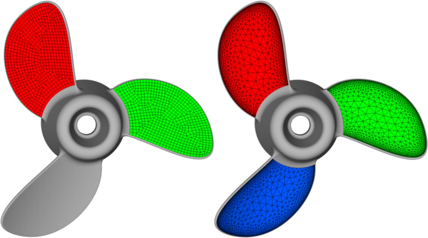
Triangles and quadrilaterals can be generated using three different modes: full triangle mesh (default), quad-dominant mesh, and full-quad mesh.
- Triangular Meshes: Default for unstructured meshing.
- Quad Dominant Meshes: Used for smoother transitions.
- Hybrid Meshes: Best for simulation efficiency.
2. Control Mesh Sizing
Once you have chosen the type of elements you want to generate, the more important question is how to control the mesh size. Two concepts usually come into play: physical (or absolute) sizing, and geometric (or feature-based) sizing, along with a third hybrid approach:
- Physical Sizing: uses a user-defined target size everywhere to generate meshes with a consistent size. Flat surfaces and details are well captured, and the curvature is approximated
- Geometric Sizing: use to automatically adapt element size based on surface curvature and geometric tolerances. Curved areas are well captured, however, the mesh is usually coarse with some high aspect ratio elements.
- Hybrid Approach: balancing both concepts can be a useful approach. Flat details and curves are well captured while maintaining a good quality for the elements. This method provides the best of both worlds.
When choosing your mesh sizing, each method should be considered within the context of the application and the type of requirements you have. General rules for selecting a mesh size are as follows:
Use a constant global size when geometry accuracy is not critical and the solver is sensitive to very small elements, e.g., the CFL condition for finite difference solvers.
Use a geometry-based size when the model contains fine features or high curvatures that must be respected to accurately capture the physics.
Apply an appropriate gradation level to avoid abrupt changes between neighboring elements, since solvers can be sensitive to sharp transitions in element size.
Pro Tip: The maximum size is small enough to be compatible with the level of detail you want to capture. The minimum size is large enough to prevent a high number of elements, and too small elements (that may prevent a smooth convergence).
3. Volume Meshing Considerations
There are criteria to take into consideration when moving to volume meshing. This is due to the number of cells generated, which are usually more critical and can significantly impact the time it takes to complete the simulation. The goals for volume meshing are to find a compromise between the number of cells and the time it takes to run the simulation. Here are our recommendations:
- Simplify Models: Remove small features or holes that don’t impact results. For example, small details may not be relevant to model the structural integrity of the entire structure and its response to fatigue, so it may be best to remove them.
- Use Symmetry: Reduce complexity by modeling repetitive patterns. This can mean reducing the geometry to the most relevant part in cases of symmetry, axi-symmetry, or repeating patterns.
- Smart Element Placement: Focus high-density elements where needed. You can control the location of the generated volume elements; all domains or limited to the exterior volume.
For simple volume workflows, sizing is relatively straightforward. The gradation is used to grow elements from the surface mesh size. Volume elements are generated from the surface mesh element size without any sizing constraints.


Volume Gradation = 1.05 Volume Gradation = 1.5 Volume Gradation = 1.9
Caption: Examples of gradation to grow elements from the surface mesh size
Pro Tips: Use controls over the maximum and minimum element sizes acceptable in the generated mesh. Use Hexahedral elements to fill the majority of the volume, and use tetra and other types to manage the transition with the surface.
Advanced Meshing Workflows
Set of geometry preparation and modeling functionalities to make CAD models ready for meshing for various applications downstream. Preparing CAD models for high-quality meshing often requires repairing BREP topology (removing slivers, short edges, gaps, and misalignments), uniting bodies for conformal meshing or simplifying geometry without affecting solution accuracy.
Apply different mesh sizes to different geometry regions. Examples include using different size constraints on the same piece of geometry, the anisotropic size of CAD faces, and volume size constraints.
“Copy and paste” mesh structures for repeated patterns. Mesh periodicity is the process of generating the same mesh on two matching CAD faces. This is useful when there are repeating patterns in the geometry to ensure consistency and that the same behaviors are observed across the entire geometry.
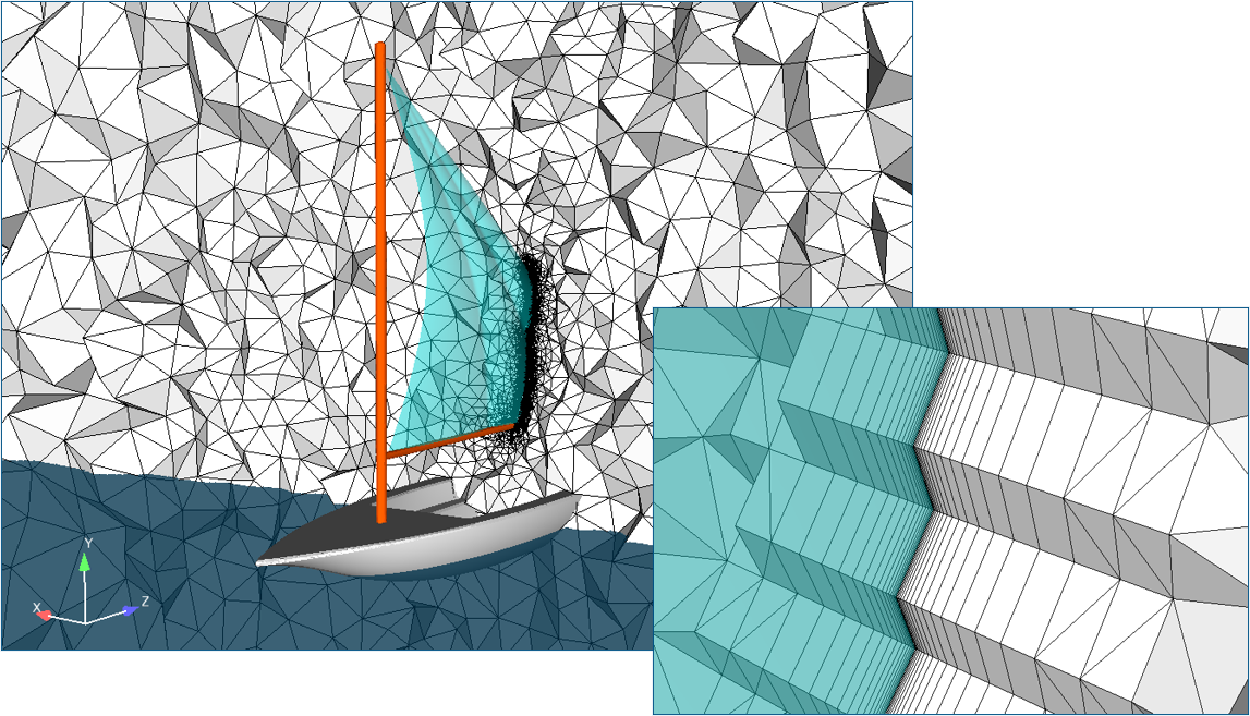
Essential for CFD applications, ensuring stable simulations. Boundary layers in a mesh are semi-structured grids grown from the surface mesh. The transition from the boundary layers to the isotropic elements within the volumes is automatically managed.
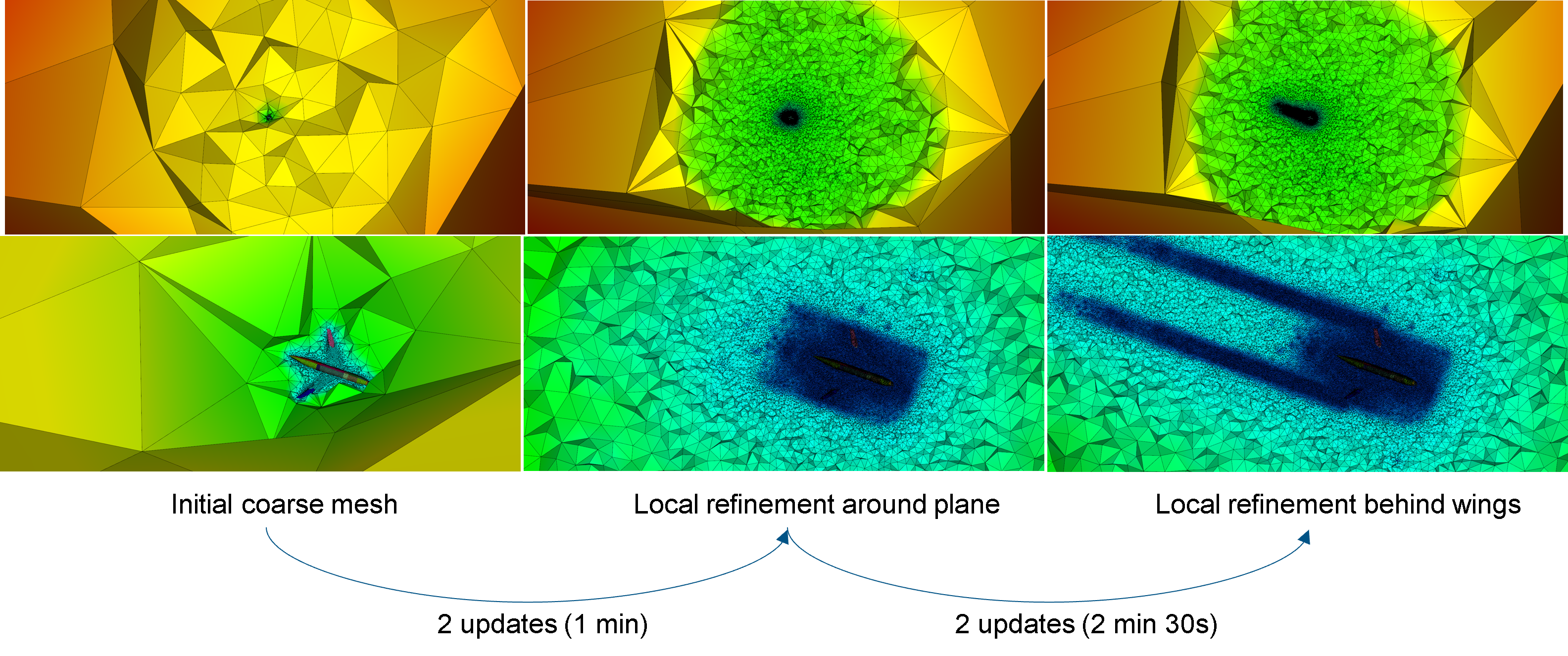
Refining meshes dynamically for better accuracy. This workflow starts with a initial coarse mesh, goes to a local refinement around the plane, and ends with a local refinement behind wing tips, with two updates in between each stage.
Integrating High-Quality Simulation-Ready Meshes
3D meshing capabilities are integral to CAE applications. Choosing the right mesh type and sizing, and understanding volume meshing constraints, are best practices that Spatial’s meshing SDKs help facilitate. Spatial’s meshing solutions provide robust and customizable tools for application developers looking to integrate high-quality simulation-ready mesh workflows.
There’s more where this came from. Check out our blog for tips, industry-specific uses for our SDKs, and product updates.
Discover the potential of Spatial solutions: Request an Evaluation
Related Read: How to Optimize the Meshing Process for CFD and FEA
About Spatial Corp
Spatial Corp, a Dassault Systèmes subsidiary, is the leading provider of 3D software development toolkits for technical applications across a broad range of industries. Spatial 3D modeling, 3D visualization, 3D Meshing and CAD translation software development toolkits help application developers deliver market-leading products, maintain focus on core competencies, and reduce time-to-market. For over 35 years, Spatial’s 3D software development toolkits have been adopted by many of the world’s most recognized software developers, manufacturers, research institutes, and universities. Headquartered in Broomfield, Colorado, Spatial has offices in the USA, France, Germany, Japan, China, and the United Kingdom. For more information on Spatial’s latest updates and product offerings, please visit www.spatial.com.

.jpg?width=450&name=AdobeStock_487440650%20(1).jpg)


