


3D computer-aided design (CAD) files are integral to today’s manufacturing processes. On the surface, the idea is sound: an engineering team will design a part and, in turn, will send the necessary 3D CAD files to the manufacturer to produce the part.
There’s an expectation that the design to the manufacturing process is seamless, which should - as a consequence - help all parties control costs and accelerate time-to-market.
However, the reality is far from perfect. Common to most processes is the bottleneck of errors and inaccuracies in 3D CAD data when one format (e.g. SLDPRT) is read in another CAD suite.
Granted, SolidWorks does command the highest share of worldwide CAD adoption, but others - such as AutoCAD, CATIA, and CREO - are in widespread use, so the prospect of different CAD workflows is certainly a factor. However, as are the risks involved with 3D data errors.
How are 3D CAD Files Used in Manufacturing?
The client, which could be an engineering or design firm, would typically send a 3D CAD file to a manufacturer to produce the part. 3D CAD files enable the manufacturer to understand how that individual part would work with other parts (i.e. as part of a system).
The Additive Manufacturing Process Flow
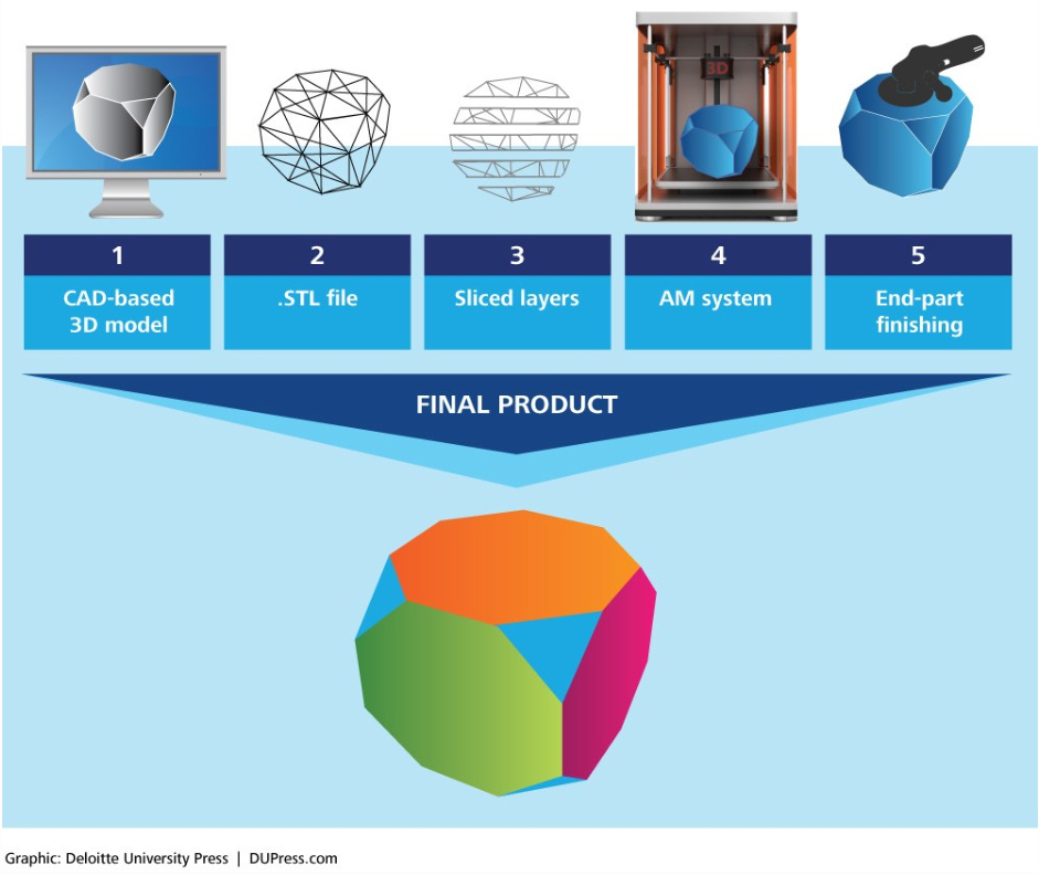
Furthermore, the ability to see the part’s geometry, physical volume and other insights equip the manufacturer to understand how much of the required material (e.g. metal) they need in order to manufacture the part, especially in big batches.
Today’s manufacturing machines - be it CNC (i.e. subtractive) or 3D printers (i.e. additive) - are able to accept 3D files, which they can use as maps or templates for cutting (CNC) or layering (3D printers).
You might also like:
-
The Impact of Model-Based Definition on 3D Modeling & Manufacturing
-
Overlap Between 3D Modeling Visualization and Gaming
In theory, the process can be a digital one from design to manufacturing as long as the 3D data remains intact when shared between different workflows.
In fact, this is the intent behind model-based definition (MBD), i.e. a situation where the
“CAD model becomes more than the nominal to which all parts are measured and inspected against … [it] keeps the all-important digital thread intact … from design to manufacturing to inspection and quality reporting.”
MBD enables every party involved in the development of the product to benefit from increased efficiency, reduced costs and quicker time-to-market.
Likewise, Product and Manufacturing Information (PMI) contributes to MBD by ensuring that the part’s necessary information is available to all downstream bodies.
PMI enables manufacturers to readily understand how to optimally cut the part and/or the part’s required material resources (in optimal quantities) with limited need to modify the design and delay the process.
How Does 3D Quality Affect Manufacturing?
Overall, the loss of 3D data fidelity or quality mitigates the advantages of sharing 3D CAD files - such as the seamlessness reducing the time-to-market - in the first place. This manifests in key areas, not least poor tessellation accuracy and inaccurate geometry from errors in source data.
Accurately translating CAD files between different CAD suites is necessary; if the 3D data is not translated correctly, you will have difficulty in the subsequent steps of materializing the part.
For example, errors may force your team into many engineering man-hours for making the CAD file readable and, following that, additional hours for design optimizations and changes.
This has major impacts. First, it adds another layer of costly engineering work which translates into higher fiscal costs and delays. Second, it adds an unnecessarily complicated layer of work.
For example, your manufacturing team might have recommendations, which they will make in their CAD suite. However, showing those changes would require manual changes to the CAD file to make it compatible with the original designer’s workflow.
This process could repeat itself multiple times between the manufacturer and the original designer, i.e. adding to your costs.
You might also like:
- Leveraging 3D Software Development Toolkits as Buildings Move into the Digital Age
- How Poor 3D Data Translation Can Derail Project Timelines and Costs
In addition, you could also run into quality control issues. Wrong or incomplete 3D file data can result in you producing parts incorrectly, which could surface downstream to the final assembly partner or, potentially the end-user.
Granted, some manufacturers could detect these problems much earlier on, but resolving them will only add to your delays and costs.
What Can Be Done to Improve 3D Data Quality in Manufacturing?
Ultimately, the actual systems involved in the design and manufacturing process would need to be improved in order to reduce 3D data errors (when CAD files are transferred from engineering or design teams to manufacturers).
This can be done by enabling manufacturers to readily read and work with 3D CAD files of different formats within their existing workflows and tools.
Spatial’s 3D InterOp is a software development kit (SDK) that equips developers of CAD suites and manufacturing hardware (such as machining tools and 3D printers) to equip their respective systems to read a wide-array of different CAD file formats..png?width=900&name=pasted%20image%200%20(1).png)
3D InterOp lets your applications and hardware to properly recognize the geometrical models in CAD files along with the models’ manufacturing and process data (e.g. PMI). 3D InterOp equips your applications to import geometric models from many industry-leading CAD formats.
With 3D InterOp, your applications will have the ability to display non-native 3D CAD files in sufficient detail (thanks to automatic geometry and topology healing). In turn, manufacturers could readily analyze and process the files with minimal manual healing work.
The reverse - i.e. enabling the original design or engineering team to view the manufacturer’s recommendations - is also possible. 3D InterOp equips developers to integrate visualization for annotations (exactly as displayed in the source system) into their CAD reading applications.
For manufacturers, the risks - and resulting financial impact - of incorrectly displayed 3D CAD files can vary, but the outcome is generally negative. Usually, such problems manifest through cost overruns, delays, and technical complications.
3D InterOp offers a means to reduce such risks and costs, which offers companies supplying software and hardware solutions to manufacturers a strong competitive edge.
Start today by contacting Spatial and evaluating how 3D InterOp SDK can place your software and hardware solutions ahead of those in the competition.
.png?width=450&name=AdobeStock_188705270%20(2).png)


.jpeg?width=450&name=AdobeStock_289023609%20(2).jpeg)


.jpg?width=450&name=Application%20Lifecycle%20Management%20(1).jpg)


