

1. Hybrid geometry representations: pick one and lose
Why a single representation is a trap
Betting on a single geometry representation is probably the biggest architectural mistake we see teams make. It feels clean at first — pick B-Rep or mesh, build everything around it, ship fast. Then reality shows up. A customer sends a scanned point cloud that needs to blend with parametric CAD. Another needs subdivision surfaces for organic shapes alongside precise analytical geometry. Your clean architecture becomes a conversion bottleneck, and you're writing glue code for the next two years.
Real modeling workflows are messy. They mix boundary representation (B-Rep) for precision, mesh for simulation and rendering, and subdivision surfaces for freeform organic shapes. The question isn't which representation is "best" — it's whether your kernel can hold all of them without falling apart at the seams.
How Spatial's kernels handle this
At Spatial, we've approached this from two directions. CGM Modeler handles B-Rep with full NURBS surface support and polyhedral models through CGM Polyhedra, all accessible through the same C++ interfaces. You don't need separate pipelines for separate representations. ACIS takes a similar approach: polyhedral modeling lives alongside B-Rep through ACIS Polyhedra, and its Laws functions let you define custom procedural geometry that the kernel treats as a first-class citizen.
The practical test: can your engine work with mixed representation types in the same model, moving between polyhedral and B-Rep data without lossy conversions at every step? If not, you're going to have problems as workflows get more heterogeneous.
We'd push back on any architecture that forces a representation choice at the foundation level. The surface types your customers need in three years aren't the ones they need today. Building for representation flexibility now is cheaper than retrofitting it later.
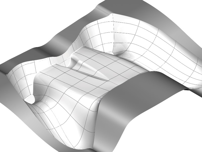
2. Continuity management: what survives the operation matters
A quick refresher on why continuity matters
Continuity gets talked about like it's a checkbox — "yes, we support G2 continuity" — when the real question is far more interesting and far more revealing of a kernel's quality.
G0 means surfaces touch (positional continuity). G1 means they share a tangent direction across the boundary. G2 means curvature is continuous — no abrupt changes in reflection lines. G3 gives you continuous rate-of-curvature change, which matters for Class A automotive surfaces where light reflections need to flow without any visible disruption.
Most kernels can represent high-continuity surfaces. That's table stakes.
The question most teams forget to ask
What continuity does the kernel guarantee after you perform operations on those surfaces?
You built a beautiful G2 fillet network. Now Boolean it with another body. Offset it. Trim it. What's left?
CGM Modeler's advanced surfacing operators — blending, covering, sweeping — are designed to preserve geometric integrity through chains of operations, not just at the moment of creation. The goal is that downstream features inherit the quality of upstream surfaces rather than silently degrading them.
We've seen teams build impressive surface creation tools that produce gorgeous initial geometry, only to watch quality fall apart the moment someone runs a Boolean or a shelling operation. The modeling kernel's job isn't just to create good surfaces. It's to keep them good while you do real work on them.
If you're evaluating kernels, don't just test surface creation. Create a complex G2 surface network, run twenty operations on it, then check what you actually have. That's the test that matters.
3. Modularity and embedding: learning from expensive mistakes
The build-vs-buy decision that costs teams years
There's a case study we keep coming back to because it's painfully common. FVA GmbH, a German engineering software company focused on drivetrain simulation, built their own custom geometry handling. It worked for a while. Then their requirements grew, edge cases multiplied, and they hit walls that would've taken years of dedicated geometry development to break through. They moved to ACIS and got back to building what actually differentiated their product.
The "build vs. buy" decision for geometry kernels is one of the most consequential architectural choices a software team makes, and teams consistently underestimate what "build" actually costs over a decade.
What embedding-first design looks like
Both ACIS and CGM are SDKs designed from the ground up for embedding. That's a different animal from a geometry library that got retroactively opened up for external use. Embedding-first design means clean API abstraction layers, sensible memory management patterns, and the ability to extend kernel behavior without forking it.
ACIS's Laws functions deserve specific mention. They let you define custom mathematical functions that the kernel evaluates natively — custom curve laws, surface laws, even procedural geometry that participates in Booleans and other operations as though it were built-in geometry. That's extensibility at the right level: deep enough to matter, clean enough not to create maintenance nightmares.
The maturity factor
ACIS has over 30 years of production history. CGM is the kernel running inside CATIA — a widely-used, demanding CAD environments. When we say these kernels have seen your edge case before, it's not marketing language. It's statistics. Thirty years of customers sending in corrupted files, degenerate geometry, and numerically hostile models builds a robustness that no amount of clever initial design can match.
The upgrade path from a mature kernel is something teams forget to evaluate. When new surface types or representation standards emerge, a maintained SDK adds support and you pick it up at the next version. With a homegrown solution, you're writing that support yourself — assuming you even hear about the new standard in time.
4. Interoperability: where clean theory meets dirty data
The gap between "supports STEP" and "handles real STEP files"
We could write an entire article just about the distance between "my kernel can import STEP files" and "my kernel can import the STEP files that actual customers actually send." That distance is vast, and it's where most modeling pipelines quietly fall apart.
3D InterOp exists because Spatial has spent over 20 years learning exactly how wide that gap is. It supports all major CAD formats, gets used by over 300 companies, and — the part that matters for freeform surface work — includes automated healing and repair.
Why freeform surfaces are where imports break
Freeform surfaces are where B-Rep models are most fragile. A trimmed NURBS surface with a complex boundary has more ways to be slightly wrong than a simple extruded box. Gaps between faces that are technically within tolerance but cause downstream Boolean failures. Surfaces whose parameterizations don't quite agree at shared edges. Self-intersecting trim curves that look fine in a viewer but break when you try to offset them.
We've written extensively about this problem because it keeps coming up:
- Healing as an essential function — why healing isn't optional for production workflows
- Healing in 3D interoperability — the specific repair strategies that work
- Why form matters in B-Rep translation — why the shape of geometry changes during translation, even when the math looks correct
- How healthy is your B-Rep? — diagnostic thinking for evaluating model quality
Your customers' data will come from systems you haven't heard of yet, in format versions that don't exist yet, with quality levels that would make your test suite weep. Building on a translation layer with two decades of real-world exposure is worth more than building on one with a clean architecture and no production mileage.
5. Tolerance handling: the invisible architecture decision
Why fixed tolerances break down
Tolerance management only gets attention when something goes wrong — and by then, it's usually baked so deeply into your architecture that fixing it means rewriting half your kernel.
The core tension: mathematical geometry is exact, but computer arithmetic isn't. Every geometric operation introduces tiny errors. Over chains of operations, those errors accumulate. Your tolerance strategy determines whether that accumulation is graceful or catastrophic.
Most kernels use fixed tolerances — they pick a number, and geometry is considered coincident if it's within that number. Simple, predictable, and fragile. When imported geometry arrives with tolerances that don't match your kernel's assumptions, you either reject it or loosen your tolerances globally, which degrades everything.
CGM's tolerant modeling approach
CGM takes a different approach. Rather than demanding that all geometry meet a fixed tolerance, the kernel accepts tolerant topology inputs and works to improve tolerances as operations proceed.
CGM's default operating range handles 1µm precision with a maximum model size of 1km. That range covers everything from microfluidic chip features to architectural-scale building models, without requiring you to choose a scale at initialization time or maintain separate tolerance regimes for different parts of your model.
For freeform surfaces specifically, tolerance handling interacts with everything else in this article. A G2 surface network with loose edge tolerances isn't really G2 — it just looks G2 until you zoom in or try to manufacture it. The kernel's ability to maintain and tighten tolerances through operations is what keeps your continuity guarantees honest.
Where this all leads
Future-proofing a modeling engine for freeform surfaces isn't about picking the right feature list today. It comes down to three things:
- Flexibility in representation — because the geometry types you need will change
- Robustness in operations — because creating surfaces is easy and keeping them valid through operations is hard
- Modularity in architecture — because rebuilding your geometry foundation is something you want to do exactly zero times
At Spatial, we've watched enough teams learn these lessons the hard way that we're fairly opinionated about it. The teams that succeed long-term are the ones who build on SDKs designed for this problem rather than assuming they can solve computational geometry as a side project.
One last piece of practical advice: test with your ugliest data, not your cleanest demos. The clean stuff always works. Future-proofing means the ugly stuff works too.
Ready to future-proof your modeling engine?
- Explore Spatial's 3D modeling SDKs — including CGM Modeler and 3D ACIS Modeler — for hybrid geometry, tolerant modeling, and advanced freeform surfacing.
- Request a free evaluation to test our kernels against your most complex geometry.
- Or contact the Spatial team directly to discuss how these components fit your architecture.
.png?width=450&name=AdobeStock_188705270%20(2).png)


.jpg?width=450&name=Application%20Lifecycle%20Management%20(1).jpg)


